
Systems and methods for multi-element antenna arrays with aperture control shutters

a multi-element antenna array and aperture control technology, applied in the field of wireless communication, can solve the problems of difficult or impossible to extend the communication range, the attenuation of propagating mm-waves is very strong, and the attenuation is even higher

Inactive Publication Date: 2010-07-13
INTEL CORP
View PDF8 Cites 6 Cited by
  • Summary
  • Abstract
  • Description
  • Claims
  • Application Information

AI Technical Summary

Benefits of technology

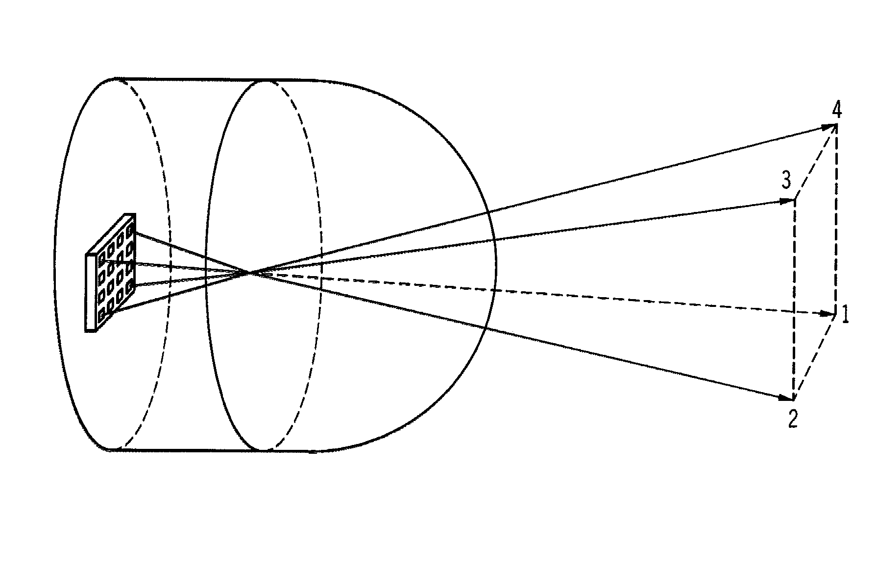
[0020]The method of external switching of antenna array elements described herein allows antenna beam control that does not require RF switches or phase shifters in the signal distribution circuit. The method of external switching is based on specially designed devices that control the radiators by ‘opening’ and ‘closing’ them. These devices herein referred to as aperture control shutters can control radiation optically by light, for example, or by applied voltage. The aperture control shutter (ACS) can be placed directly on the radiating aperture; it has two operation modes: open and close—allowing and preventing radiation, respectively. Methods described herein provide beam switching that is easy to implement at mm-wave frequencies, and that is relatively immune to production tolerances. These methods of beam control enable the building of inexpensive, high-gain and high-efficiency switched beam antenna systems suitable for mm-wave communications.
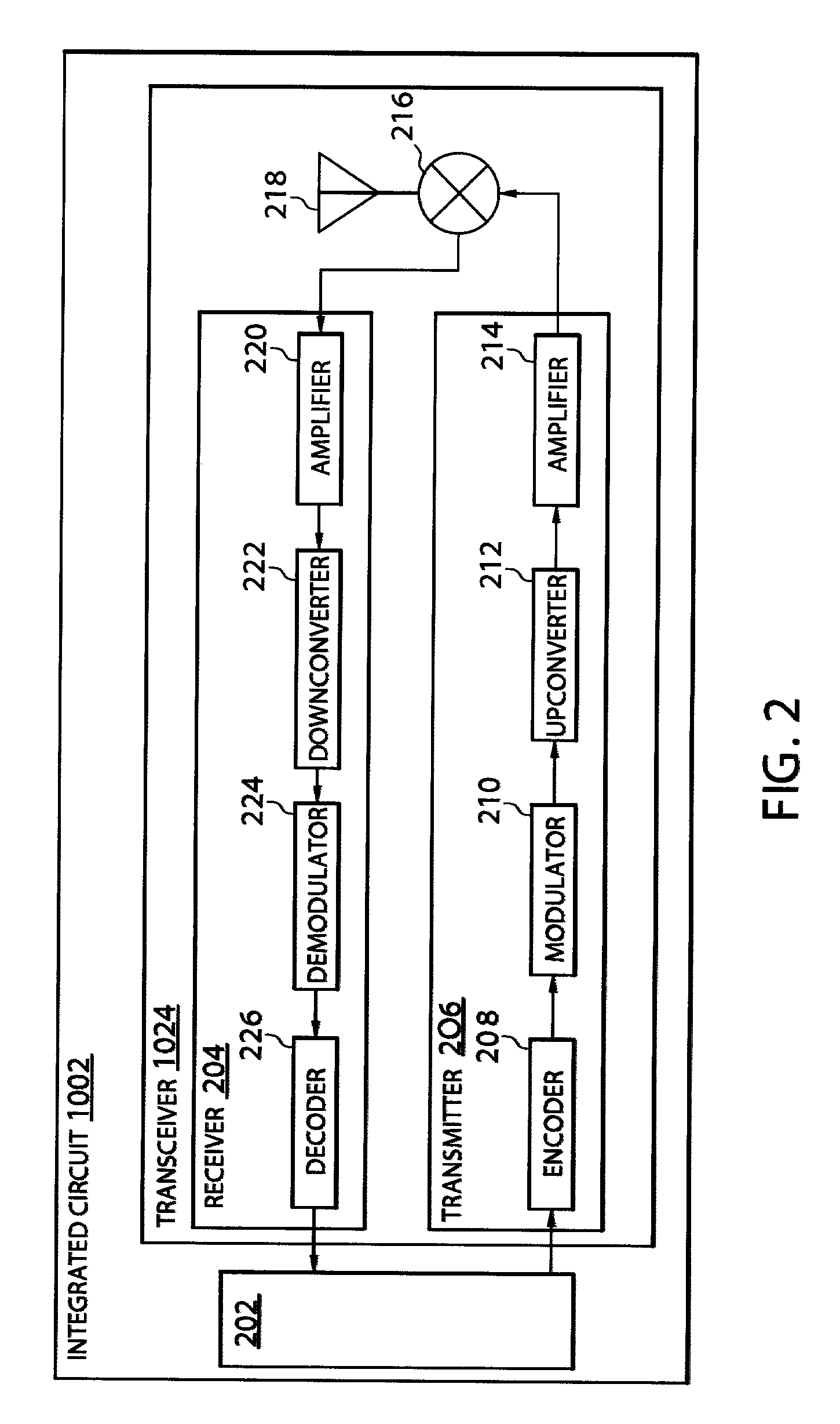
[0028]Encoder 208 of transmitter 206 receives data destined for transmission from a core 202. Core 202 may comprise a computing system such as described with reference to FIG. 1. Core 202 presents data to transceiver 1024 in blocks such as bytes of data and receives data from transceiver 1024. Encoder 208 encodes the data and may introduce redundancy to the data stream. Encoding may be done to achieve one or more of a plurality of different purposes. For example, coding may be performed to decrease the average number of bits that must be sent to transfer each symbol of information to be transmitted. Coding may be performed to decrease a probability of error in symbol detection at the receiver. Thus, an encoder may introduce redundancy to the data stream. Adding redundancy increases the channel bandwidth required to transmit the information, but results in less error, and enables the signal to be transmitted at lower power. Encryption may also be performed for security.
[0033]u⁡(t)=∑n=1∞⁢⁢ⅇjθn⁢g⁡(t-nT)where g(t−nT) is a basic pulse whose shape may be optimized to increase the probability of accurate detection at a receiver by, for example, reducing inter-symbol interference. Inter-symbol interference results when the channel distorts the pulses. When this occurs adjacent pulses are smeared to the point that individual pulses are difficult to distinguish. A pulse shape may therefore be selected to reduce the probability of symbol misdetection due to inter-symbol interference.
[0041]FIG. 2 also shows an embodiment of a receiver 204 for receiving, demodulating, and decoding an information bearing signal. The signal is fed from antenna 218 to a low noise amplifier 220. Amplifier 220 comprises filter circuitry which passes the desired signal information and filters out noise and unwanted signals at frequencies outside the pass band of the filter circuitry. A downconverter 222 downconverts the signal at the carrier frequency to an intermediate frequency or to base band. By shifting the received signal to a lower frequency or to baseband, the function of demodulation is easier to perform. Demodulator 224 demodulates the received signal to extract the information content from the received down converted signal to produce an information signal. Decoder 226 decodes the information signal received from demodulator 224 and transmits the decoded information to core 202. Persons of skill in the art will recognize that a transceiver will comprise numerous additional components not shown in FIG. 2. Note that each endpoint device has its own transceiver which operates substantially as described above.

Problems solved by technology

Thus, propagating mm-waves suffer from very strong attenuation.
Other factors such as oxygen absorption further worsen the situation making the attenuation even higher.
At mm-wave frequencies it is difficult or impossible to extend communication range by increasing transmitted power, because of difficulties implementing high power semiconductor transmitters, and because of FCC (Federal Communications Commission) limitations imposed on transmitted power.
However, high-gain antennas have narrow beam-widths, so there is a problem of antenna alignment and accurate pointing to effectuate communication with a peripheral device.
A low loss and low cost signal distribution circuit required for switching of radiators is very difficult to implement at mm-wave frequencies.

Method used


Image

  • Systems and methods for multi-element antenna arrays with aperture control shutters
  • Systems and methods for multi-element antenna arrays with aperture control shutters
  • Systems and methods for multi-element antenna arrays with aperture control shutters

Examples


Embodiment Construction

[0017]The following is a detailed description of embodiments of the invention depicted in the accompanying drawings. The embodiments are in such detail as to clearly communicate the invention. However, the amount of detail offered is not intended to limit the anticipated variations of embodiments; but, on the contrary, the intention is to cover all modifications, equivalents, and alternatives falling within the spirit and scope of the present invention as defined by the appended claims. The detailed descriptions below are designed to make such embodiments obvious to a person of ordinary skill in the art.

[0018]Embodiments include systems and methods for controlling beam direction of an array of antenna elements in a wireless communications system. In one embodiment, aperture control shutters substantially cover each radiating antenna element. Each aperture control shutter is selectively turned on or off to control the direction of a beam of the antenna array.

[0019]The wireless commun...


PUM


Abstract

Embodiments include systems and methods for controlling beam direction of an array of antenna elements in a wireless communications system. In one embodiment, aperture control shutters substantially cover each radiating antenna element. Each aperture control shutter is selectively turned on or off to control the direction of a beam of the antenna array.

Description

FIELD[0001]The present invention is in the field of wireless communications between a host computing system and multiple endpoint devices. More particularly, the invention is in the field of management of remote pipe resources in a wireless adapter.BACKGROUND[0002]“Wireless computing” is a term that has come to describe wireless communications between computing devices or between a computer and peripheral devices such as printers. For example, many computers, including tower and laptop models, have a wireless communications card that comprises a transmitter and receiver connected to an antenna. Or alternatively, a Host Wire Adapter (HWA) is connected to the computer by a USB (Universal Serial Bus) cable. The HWA has an RF (Radio Frequency) transmitter and receiver capable of communicating data in a USB-cognizable format. This enables the computer to communicate by RF transmission with a wireless network of computers and peripheral devices. The flexibility and mobility that wireless ...

Claims


Application Information

Patent Timeline
Patent Type & Authority Patents(United States)
IPC IPC(8): H04B7/14
CPCH01Q3/2658H01Q13/10H01Q19/062
Inventor ALAMOUTI, SIAVASHMALTSEV, ALEXANDER A.CHISTYAKOV, NIKOLAY
Owner INTEL CORP
Learn More