Apparatus and method for catheter guidance control and imaging

a catheter and guidewire technology, applied in the field of system and technique for guiding, steering, and advancing invasive medical devices, can solve the problems of difficult to advance the guidewire to the stenosis, time-consuming and time-consuming technical difficulties encountered during angioplasty procedures, and the operator needs great skills that can only be achieved, so as to reduce the exposure of x-ray and contrast material, less training, and less skill

Inactive Publication Date: 2010-08-03
NEURO KINESIS CORP
View PDF166 Cites 159 Cited by
  • Summary
  • Abstract
  • Description
  • Claims
  • Application Information

AI Technical Summary

Benefits of technology

[0018]The present invention solves these and other problems by providing a magnetic catheter guidance and control apparatus that requires less training and less skill than prior art systems. The magnetic catheter guidance system can rapidly advance and position the catheter, thus minimizing x-ray and contrast material exposure. Moreover, the magnetic system used in the magnetic catheter guidance system can be used to locate the catheter tip to provide location feedback to the operator and the control system.
[0019]One embodiment includes a catheter and a guidance and control apparatus that can accurately, and with relative ease, allow the surgeon / operator to position the catheter tip inside a patient's body. The catheter guidance and control apparatus can maintain the catheter tip in the correct position. One embodiment, includes a catheter with guidance and control apparatus that can steer a guidewire or balloon through arteries and forcefully advance it through plaque or other obstructions. One embodiment includes a catheter guidance and control apparatus that displays the catheter tip location with significantly reduced x-ray exposure to the patient and staff. One embodiment includes a catheter guidance and control apparatus that is more intuitive and simpler to use, that displays the catheter tip location in three dimensions, that applies force at the catheter tip to pull, push, turn, or hold the tip as desired, and that is capable of producing a vibratory or pulsating motion of the tip with adjustable frequency and amplitude to aid in advancing the tip through plaque or other obstructions. One embodiment provides tactile feedback at the operator control to indicate an obstruction encountered by the tip.
[0020]In one embodiment, a catheter Guidance Control and Imaging (GCI) apparatus allows a surgeon to advance, accurately position and fixate a catheter, and to view the catheters' position in three dimensions with the x-ray imagery overlaying the display. In one embodiment, the apparatus includes an operator control called a “Virtual Tip” which, in addition to being a model representation of the actual or physical catheter tip advancing within the patient's body, possesses a positional relationship to the catheter tip.
[0023]The operator control provides the position and orientation command inputs to a servo system that controls the catheter tip position by regulating the magnetic force applied outside the patient's body. A measurement of the actual tip position and orientation is made via sensory apparatus that includes magnetic field sensors and temperature sensors. This measurement serves as a feedback to the servo system and the operator interface. In one embodiment, the servo system has a correction input that compensates for the dynamic position of a body part or organ, such as the heart, thereby offsetting the response such that the actual tip moves in unison with the beating heart.

Problems solved by technology

This technique requires great skills on the part of the operator that can only be achieved after a protracted training period and extended practice.
The time consuming technical difficulties encountered during angioplasty procedure are similar to those associated with angiography.
If the artery to be treated is torturous with sharp bends, it may be difficult to advance the guidewire to the stenosis.
If the stenosis is severe or the artery is totally blocked, it may be difficult or even impossible to properly position the guidewire.
These technical difficulties can render the procedure unfeasible.
Crossing the narrowed valve orifice is a challenge to the operator.
In these situations the placement of a guidewire beyond the narrowed site is very difficult and many times unsuccessful.
Many times, the manipulation to place the electrodes in a proper position is difficult and the results are sub-optimal due to anatomical variations.
This can be a cumbersome and time-consuming procedure because multiple measurements are often required to perform a complete study.
In addition, accurately positioning the electrode using manual manipulation is a difficult process.
Given these exacting requirements, the imprecise nature of manual manipulation can cause this procedure to be especially difficult and time consuming.
Notwithstanding a high success rate and a low risk of recurrent restenosis associated with this procedure, a known complication is an atrial septal defect induced by the puncture of the intra-atrial septum.
Although much less aggressive than surgery, this procedure is lengthy, difficult, and requires special skills in addition to those normally requisite for catheterization.
Because a relatively rigid balloon is required to break the tissue narrowing the mitral valve, it is almost impossible to bring the balloon into proper alignment via the aorta and left ventricle due to the sharp acute angle between the aortic route and the required approach to the mitral valve.
Due to the accuracy required when positioning and fixating the laser catheter, this procedure does not appear to be implementable with currently available catheter technology.
The foregoing procedures suffer from numerous disadvantages and limitations.
Many of the procedures are tedious and time-consuming.
This results in repeated and prolonged exposure of the patient and staff to the adverse effects of x-rays.
The lengthy procedures also require the use of additional contrast material with associated risk to the patient.
Procedures that require highly-accurate positioning of the catheter distal end (also referred to as the catheter tip) are difficult to perform and are not always feasible.
The insertion, removal, and manipulation of secondary tools often causes the tip of the guiding catheter to be dislodged from the desired position.
Time-consuming manipulation is required to correctly reposition the tip.
The coronary arteries are sometimes torturous with sharp bends or blockages that make advancement of a guidewire or balloon difficult or even impossible.
Therefore, there is a great and still unsatisfied need for an apparatus and method for guiding, steering, and advancing invasive devices and for accurately controlling their position; for providing three dimensional imaging; and for minimizing the use of x-rays or other ionizing-type radiation

Method used


Image

  • Apparatus and method for catheter guidance control and imaging
  • Apparatus and method for catheter guidance control and imaging
  • Apparatus and method for catheter guidance control and imaging

Examples


Embodiment Construction

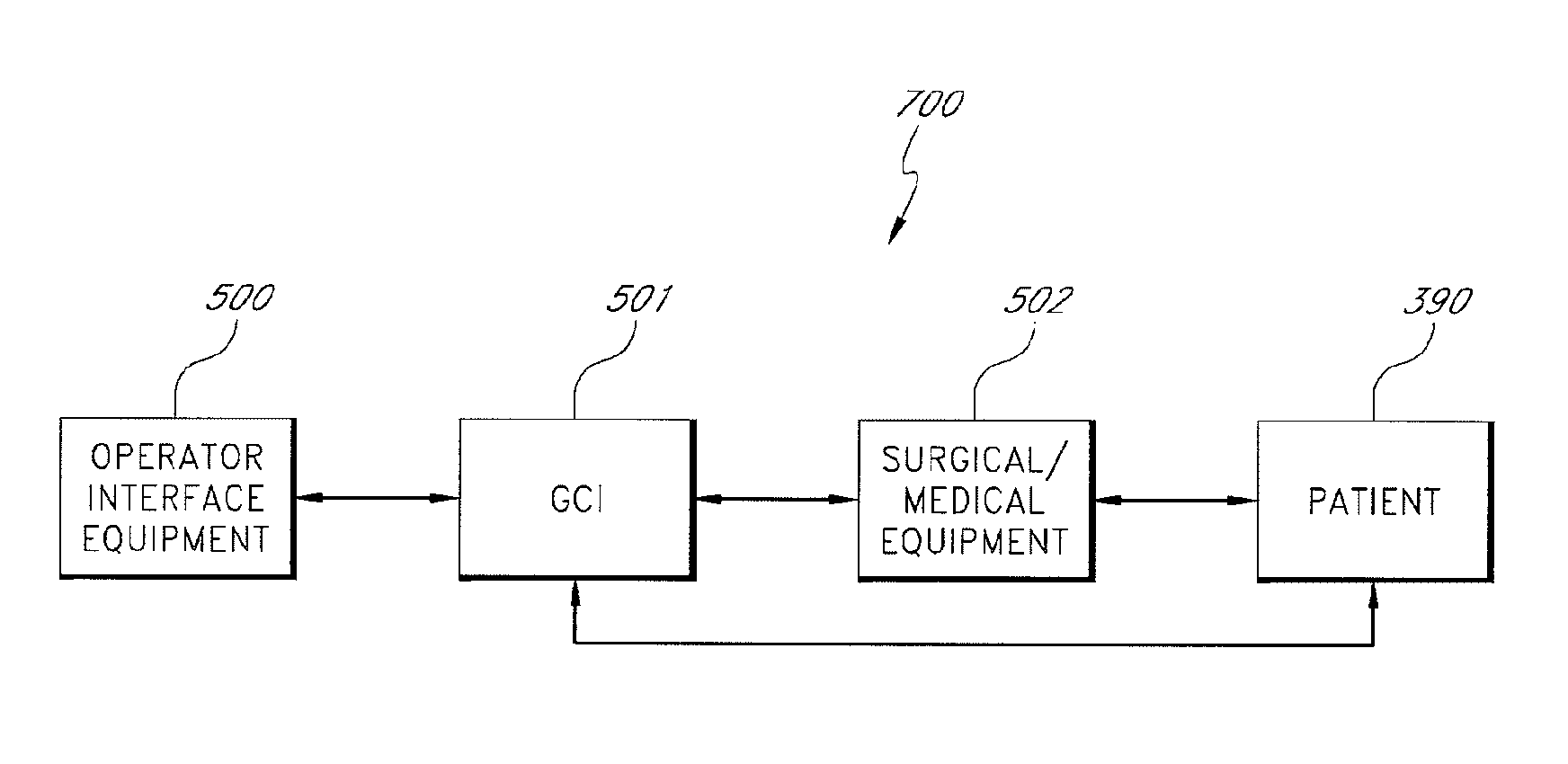
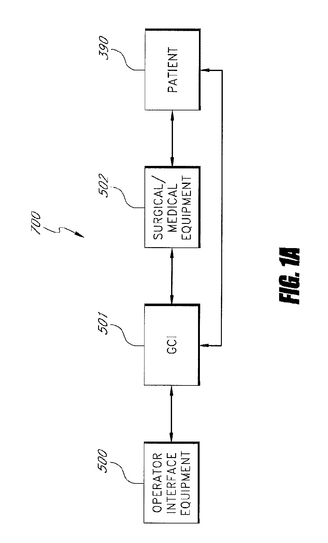
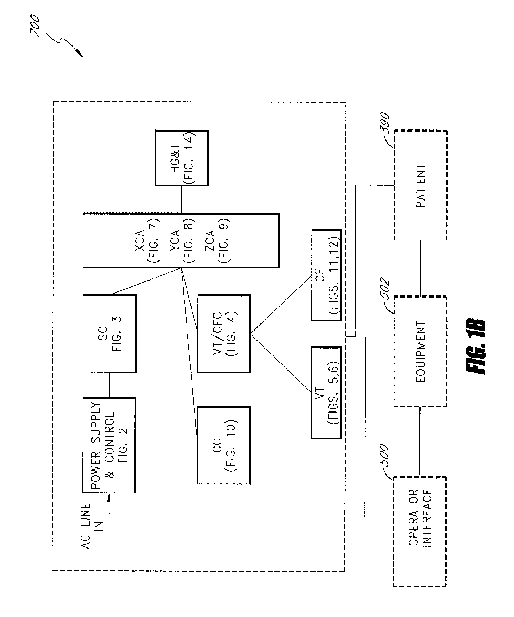
[0072]FIGS. 1A, 1B and 1C show a system 700 that includes a guidance, control, and imaging (GCI) apparatus 501. The system 700 further includes an operator interface equipment 500 and a surgical medical equipment 502. FIG. 1A illustrates an embodiment of the GCI apparatus 501 that includes various functional units. FIG. 1A further illustrates the overall relationship between these functional units and the operator interface 500, the auxiliary equipment 502 residing in the operating room, and the patient 390. FIG. 1B provides further details of the inter-relationships of these functional units and some of their components.

[0073]FIG. 1C shows the inter-relation between the GCI apparatus 501, surgical medical equipment 502, operator interface equipment 500, and a reference patient 390. A more detailed description of the GCI apparatus 501 and other auxiliary equipment, such as the surgical medical equipment 502, in the operating room will be described later in greater detail in connecti...


PUM


Abstract

A system whereby a magnetic tip attached to a surgical tool is detected, displayed and positioned. A Virtual Tip serves as an operator control. Movement of the operator control produces corresponding movement of the magnetic tip inside the patient's body. Additionally, the control provides tactile feedback to the operator's hand in the appropriate axis or axes if the magnetic tip encounters an obstacle. The output of the control combined with the magnetic tip position and orientation feedback allows a servo system to control the external magnetic field by pulse width modulating the positioning electromagnet. Data concerning the dynamic position of a moving body part such as a beating heart offsets the servo systems response in such a way that the magnetic tip, and hence the secondary tool is caused to move in unison with the moving body part.

Description

REFERENCE TO RELATED APPLICATIONS[0001]The present application claims priority from U.S. Provisional Patent Application No. 60 / 396,302, filed Jul. 16, 2002, titled “CATHETER GUIDANCE CONTROL AND IMAGING APPARATUS AND METHOD,” the entire contents of which is hereby incorporated by reference.BACKGROUND[0002]1. Field of the Invention[0003]The present invention relates to systems and techniques for guiding, steering, and advancing invasive medical devices such as catheters and catheter-type devices.[0004]2. Description of the Related Art[0005]In general, catheterization is performed by inserting an invasive device into an incision or a body orifice. Secondary tools such as guidewires and balloons are often advanced along the primary catheter to the area where the medical procedure is to be performed. These procedures rely on manually advancing the distal end of the invasive device by pushing, rotating, or otherwise manipulating the proximal end that remains outside of the body. Real-tim...

Claims


Application Information

Patent Timeline
Patent Type & Authority Patents(United States)
IPC IPC(8): A61B5/05A61B17/00A61B1/00A61B5/06A61B17/22A61B19/00A61M25/01
CPCA61B5/06A61B17/22A61B19/22A61B19/5244A61B5/062A61M25/0158A61B2017/00084A61B2017/003A61B2017/00703A61B2019/2211A61B2019/2253A61B2019/2261A61B2019/2276A61B2019/2292A61B2019/502A61B2019/5238A61B2019/5251A61B2019/5291A61B2019/5454A61B34/73A61B2034/732A61B2034/742A61B2034/102A61B34/20A61B34/70A61B2034/301A61B2090/376A61B34/76A61B2034/2051A61B2090/365A61B2090/3954A61B5/7455
Inventor SHACHAR, YEHOSHUA
Owner NEURO KINESIS CORP
Why Eureka
Try Eureka