[0004]It is accordingly the principal object of the present invention to provide apparatus by which loading of substrates onto and unloading of substrates from, for example, a substrate holder can be accomplished in an automated manner, i.e. without the need for direct manual intervention in the loading and unloading zone, in a vacuum environment so that the vacuum can be maintained between
processing actions on successive substrates.
[0008]Substrate loading and unloading apparatus of this kind is particularly suitable for use as part of an automated substrate loading and unloading
system in a substrate
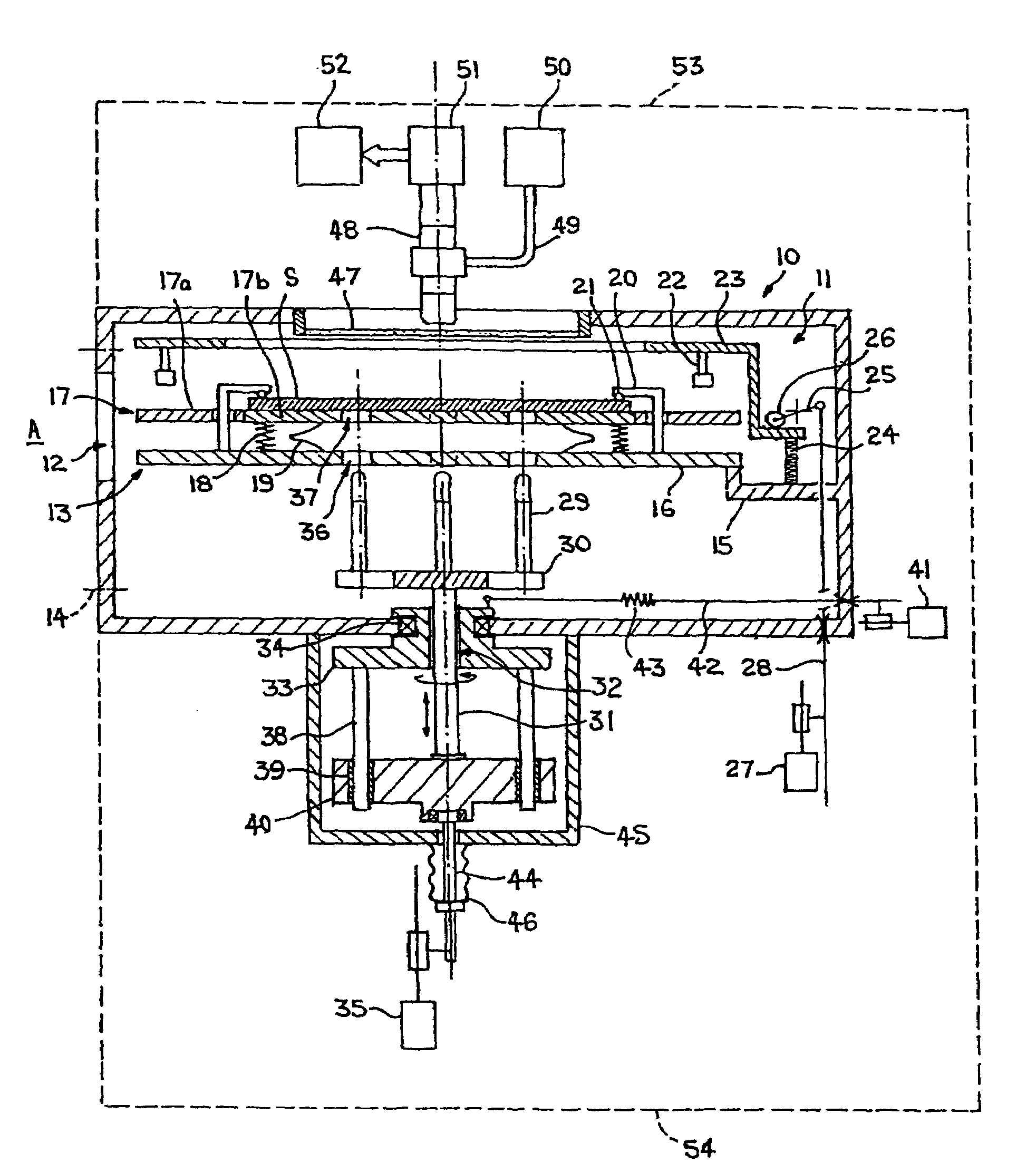
processing machine in which processing has to be carried out in a vacuum environment. Through communication of the loading and unloading chamber of the apparatus with the evacuated region of the machine by way of the transfer port of the chamber, the vacuum environment is extended to the apparatus, which thus does not require an own vacuum-generating
system. Rather than removal from the machine for substrate loading and unloading, the holder can remain within the vacuum environment and be passed back and forth between the evacuated region, in which the actual substrate processing is carried out, and the chamber, in which substrates to be processed can be loaded into and processed substrates unloaded from the holder. Transfer of the holder between the evacuated region of the machine and the loading and unloading chamber and transfer of substrates to and from the holder can be carried out by way of a remotely actuable
transfer system integrated in the machine and engaging through the transfer port. The vacuum environment can thus be constantly maintained subject only to provision for supply of further substrates to and removal of processed substrates from the machine, which can be carried out by way of an air lock affecting only a small zone of the evacuated region. Loss of processing time due to repeated relief of the evacuated region and reinstatement of the vacuum for the purpose of substrate
changeover is thus eliminated or significantly reduced. The automated vacuum loading and unloading can also reduce the
time cost for skilled personnel and the potential for handling errors of the kind occurring with manual loading and unloading externally of the machine.
[0009]Preferably, the locating means defines a
reference plane for a top face of the supported substrate. This ensures that the
critical surface of each substrate, for example the top face of a
wafer to be processed by writing of a pattern, is disposed in a consistently repeatable position. The plane is preferably defined by three spaced-apart contact points for contacting the substrate top face, so that the substrate can be pressed towards the table at locations ensuring an even distribution of force and promoting flattening of the substrates to counteract any intrinsic bowing, twisting or other
distortion of the substrates. The contact points can be provided by contact surfaces of stop members disposed above the table and fixed relative to a body member, for example a base plate, of the holder. Such contact surfaces can be flat, but for preference are rounded and can be formed by, for example, surfaces of balls of
sapphire or other suitable material with a stable temperature characteristic, in particular low coefficient of
thermal expansion. The individual stop members can extend downwardly, possibly via openings in the table, to the body member, where they can be mounted. Above the table, the stop members can extend across part of the area supporting the substrate, so that the stop members together define the
reference plane without significantly obstructing the space above the table and thereby restricting movement of substrates to and from the table.
[0010]For preference, the locating means comprises resilient means to cause a supported substrate to be biased towards the table. A resiliently applied pressing force ensures firm location of the substrate, primarily in the z-axis direction and secondarily through the friction generated by the pressing force—in the x-axis and y-axis directions, but without the possibly damaging consequences of non-yielding clamping. The resilient means preferably comprises a resilient mounting of the table, so that components defining the
reference plane can be rigidly located and are unaffected by the resilience in the locating
system.
[0012]The release means present in the apparatus preferably comprises displacing means to displace the table against the direction of bias by the resilient means, more specifically against the resilience of the table resilient mounting provided by, for example, the compression and leaf springs. The displacing means can comprise at least one displacing member movable to engage and depress the table, this movement preferably being opposed by resilient restoring means; the resilient mounting of the table will itself
resist depression of the table, but the restoring means serves more specifically to move the displacement member or members back out of engagement with the table. The or each displacing member advantageously has the form of a pusher carried by an upwardly and downwardly movable carrier member, which is located in the loading and unloading chamber, and for preference three such pushers arranged at mutual spacings are provided. The three pushers ensure an even distribution of force applied to the table during pressing of the table against the resilient mounting and the resilient restoring means and can be spaced apart sufficiently to allow unrestricted access of substrates to the holder. The displacing means may further include drive means to cause downward movement of the carrier member, such drive means comprising, for example, lever means drivably engaging the carrier member and actuating means to pivot the lever means. The lever means can comprise at least one rocker member drivably engaging the carrier member by way of a roller, the rocker member being able to be arranged to provide considerable
mechanical advantage in transmission of drive to the resiliently biassed carrier member. The actuating means can be situated outside the vacuum vessel and coupled to the lever means by way of
coupling means passing through a vacuum-tight entry passage of the vessel. In that case the actuating means, which can be, for example, a pneumatic
piston-cylinder unit, is preferably disposed below the vacuum vessel so as to assist in maintaining compact dimensions of the apparatus.
[0015]The fine adjustment facility is preferably associated with an optical system for determining the angular position of the temporarily supported substrate, such as image generating means for causing generation of an image of part of the substrate, an
image detector for detecting the image and determining means for comparing the detected image with a
reference image and determining, from the comparison result, the angular position of the substrate relative to a predetermined or target position.
Image generation can be achieved by a
light source and optical transmission means, such as a fibre-optic cable, for transmitting light from the source to produce a topographical image of part or all of the substrate top face. The
image detection can be carried out with a
microscope for detecting the image and a camera for recording the detected image and position determination can be performed by
data processing means for
software processing of data indicative of the orientation of the detected image and comparison of those data with data indicative of the orientation of the
reference image. The optical system, which can be disposed above the vacuum vessel and act via a window let into a top wall of the vessel, can be associated with control means to control the rotational movement of the temporary support means in dependence on the instantaneous substrate angular position determined by the optical system. Fine adjustment of the substrate angular position can thus be carried out in a
fully automated manner. In addition, the upward and downward movement of the temporary support means can be utilised to bring the top face of the temporarily supported substrate into a focal plane of the optical system so that the generated image is precisely focussed.

