Ceramic cores for casting superalloys and refractory metal composites, and related processes

a technology of refractory metal and composites, applied in the field of refractory metal intermetallic composites, can solve the problems of mechanical rupture of casting, difficult to achieve the required dimensional accuracy and stability, and unsatisfactory amount of shrinkage, and achieve the effect of efficient casting

Inactive Publication Date: 2010-09-21
GENERAL ELECTRIC CO
View PDF18 Cites 19 Cited by
  • Summary
  • Abstract
  • Description
  • Claims
  • Application Information

AI Technical Summary

Problems solved by technology

Turbines and other types of high-performance equipment are designed to operate in a very demanding environment which usually includes high-temperature exposure, and often includes high stress and high pressure.
However, this heat treatment can lead to an undesirable amount of shrinkage.
If the core were to exhibit shrinkage of greater than about 0.2% in some situations, the required dimensional accuracy and stability are difficult to achieve.
(Otherwise, tensile stress could lead to mechanical rupture of the casting during solidification and cooling).
As an example, when casting highly reactive materials like the RMIC's, any reaction between the casting metal and certain components in the core can result in serious defects on the interior surfaces of the cast article.
Niobium silicide castings are especially susceptible to adverse reaction when brought into contact at elevated temperatures with free silica and alumina from the core.
It can be very difficult to attain all of the advantageous characteristics for ceramic cores, by way of a single formulation.
As an illustration, while certain core materials may exhibit the high strength required for casting, they fail to exhibit the low crush strength required to prevent hot-cracking of the metal during cooling.
In other cases, core materials may exhibit the required degree of both strength and stability, but fail to possess the desired “leachability” characteristics, which can be a very serious disadvantage.

Method used


Image

  • Ceramic cores for casting superalloys and refractory metal composites, and related processes
  • Ceramic cores for casting superalloys and refractory metal composites, and related processes

Examples


example 1

[0069]A core was prepared by dry-mixing a composition based on 5% by weight aluminum metal powder with yttria. A commercial, paraffin-based hydrocarbon wax composition was also incorporated into the mixture by blending at about 90° C., to render the ceramic / binder mixture fluid-like. The composition was then extruded into test bars having dimensions of 50 mm×12.5 mm×4 mm.

[0070]A heat treatment followed, carried out in a conventional oven, with an air atmosphere. The heat treatment schedule involved three major stages: approximately 100° C.-400° C. for wax melting and removal; approximately 650° C.-1100° C. for aluminum oxidation; and then sintering at 1200° C.-1700° C. Multiple hold-times were present at various temperatures within and between the stages. The overall heat treatment time was about 50 hours.

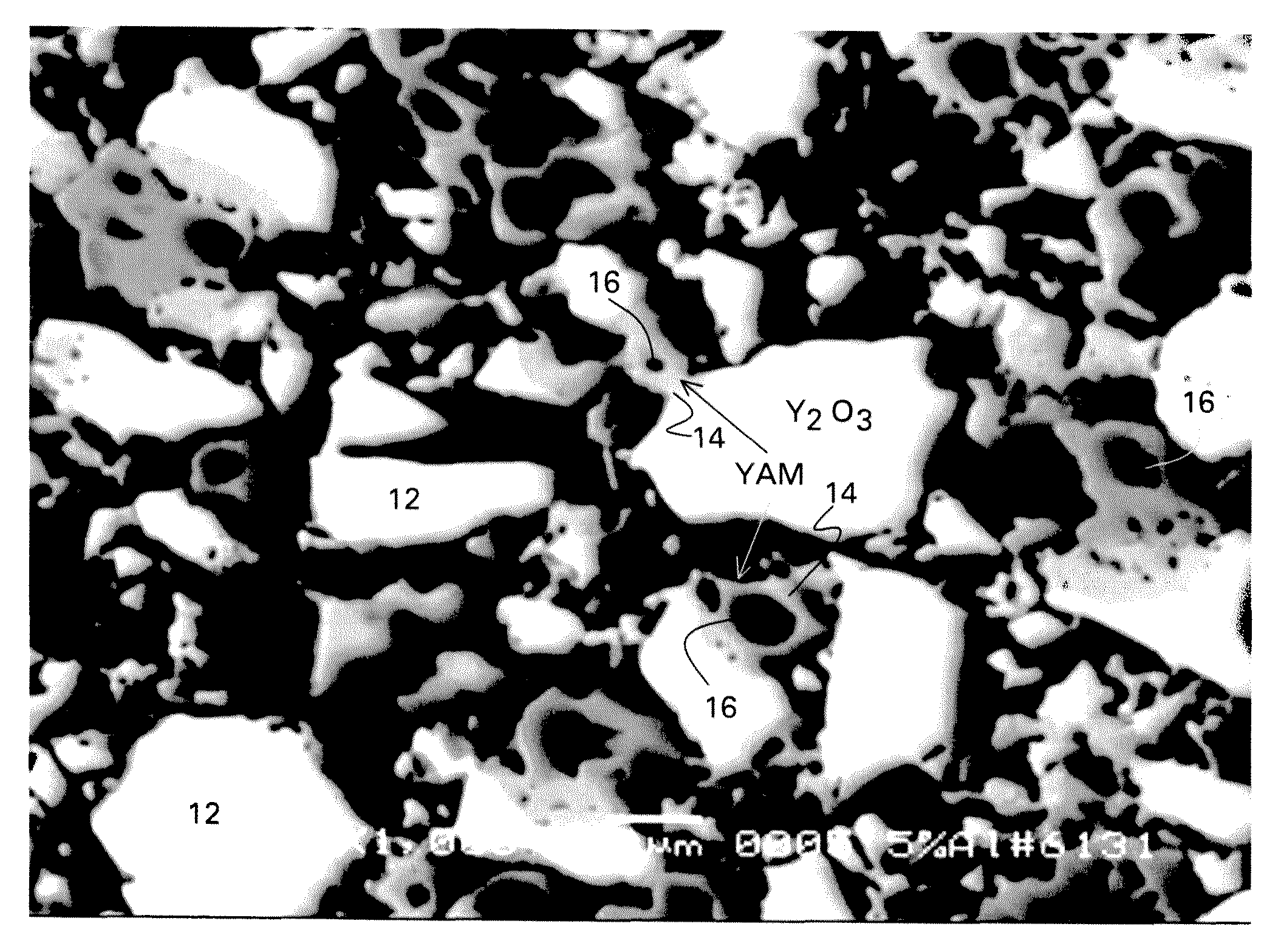
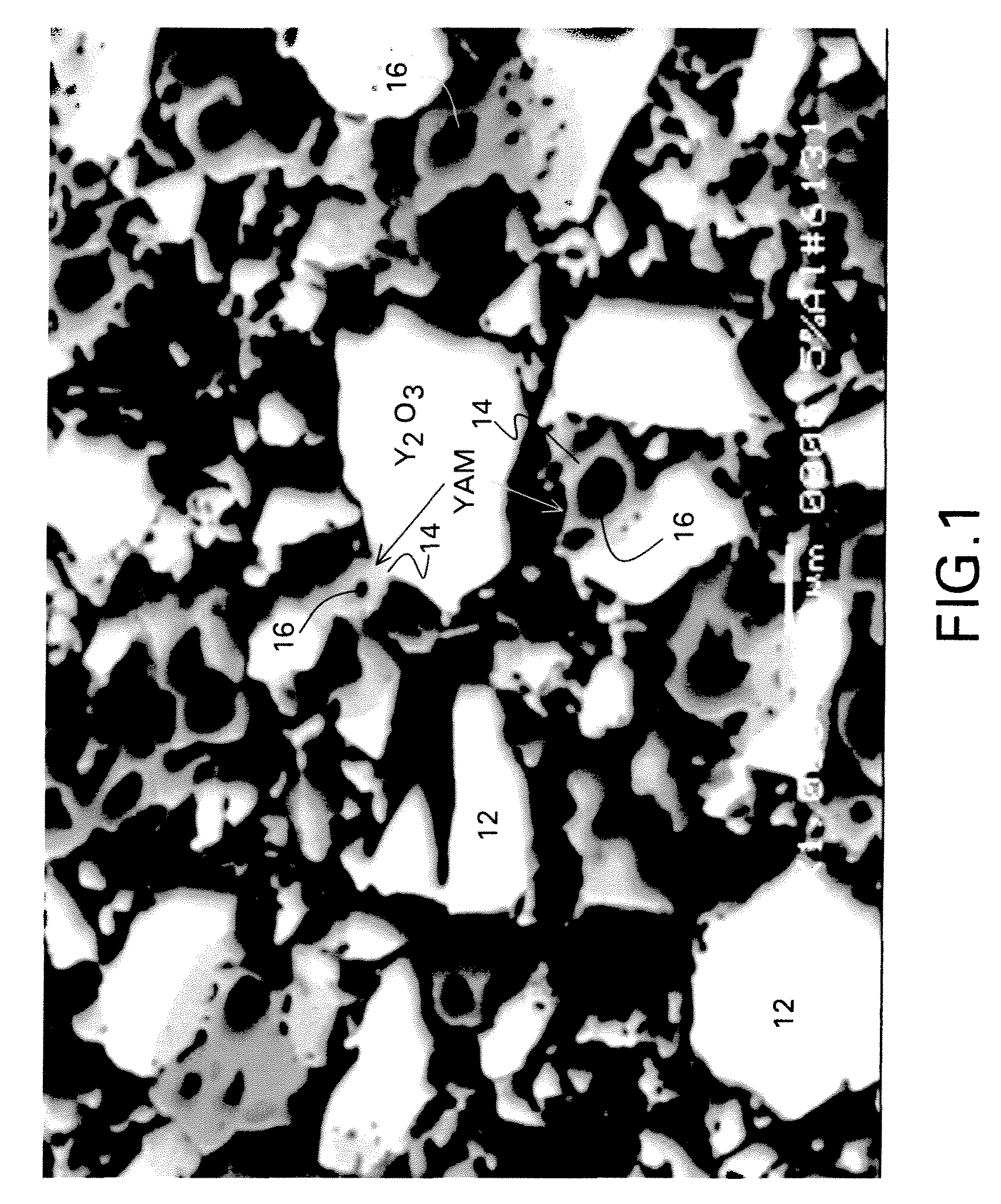
[0071]FIG. 1 is a cross-sectional SEM (scanning electron microscope), at 1000× magnification, of a test bar of the sintered material prepared generally according to the technique s...

example 2

[0073]A core was prepared by dry-mixing a composition based on 5% by weight aluminum metal powder with yttria. The hydrocarbon wax of Example 1 was also incorporated into the mixture, by blending at about 90° C., to render the ceramic / binder mixture fluid-like. The composition was then extruded into test bars having dimensions of 50 mm×12.5 mm×4.0 mm.

[0074]The samples were heated slowly at low temperatures, to completely remove the binder system from the bars. The samples were then heat-treated to a sintering temperature of 1700° C. for about 1 hour. After the final firing step, the average shrinkage of the bars was approximately 2.5% The average strength of the test bars was about 1530 psi.

[0075]One of the samples was then analyzed for the composition of the bulk phase. The sample was crushed and then mixed by hand. Quantitative X-Ray diffraction (XRD) analysis was then performed on the crushed powder, to determine the overall composition of the sample. Table 1 provides a listing o...

example 3

[0077]A core was prepared by dry-mixing a composition based on 5% by weight aluminum metal powder with yttria. As in Example 2, the hydrocarbon wax was incorporated into the mixture by blending at about 90° C., to render the ceramic / binder mixture fluid-like. The composition was then extruded into test bars having dimensions of 50 mm×12.5 mm×4.0 mm.

[0078]The samples were heated slowly at low temperatures to completely remove the binder system from the bars, and then further heat-treated to a sintering temperature of 1600° C.

[0079]One of the bars was then prepared for leaching, by weighing an initial weight of the sintered bar sample. The bar weighed 4.1 g. The sample bar was placed in a Teflon®-sealed container which also contained 69% nitric acid. The Teflon container was then placed in an oil bath of 110° C., for a total time of 4 hours. An attempt was then made to remove the sample from the container. However, only a small amount (less than 0.4 g) of residual powder remained, set...


PUM

PropertyMeasurementUnit
diameteraaaaaaaaaa
operating temperatureaaaaaaaaaa

Abstract

A rare earth-based core for use in the casting of a reactive metal is described. The core contains a ceramic composition which includes at least about 10% by weight of monoclinic rare earth aluminate (RE4Al2O9), wherein RE represents at least one rare earth element; and at least about 10% by weight of at least one free rare earth oxide. The ceramic phase of the composition may include a microstructure which comprises a multitude of substantially spherical pores which are formed as a result of the removal of aluminum metal from the core composition during a heat treatment step. Additional embodiments relate to a method for the fabrication of a ceramic core, employing a rare earth oxide, aluminum metal, and a binder. Methods for removing cores from a cast part are also described.

Description

BACKGROUND OF THE INVENTION[0001]The present invention relates generally to refractory metal intermetallic composites and methods for preparing such materials. Some specific embodiments of the invention are directed to core constructions used in casting the materials into useful articles.[0002]Turbines and other types of high-performance equipment are designed to operate in a very demanding environment which usually includes high-temperature exposure, and often includes high stress and high pressure. Turbine components have often been fabricated from a class of materials known as superalloys, which characteristically exhibit desirable chemical and physical properties under the service conditions generally experienced during turbine operation. Superalloys in which the base constituent is an alloy of nickel (Ni), iron (Fe), or cobalt (Co) are of particular interest in such applications, because of their ability to withstand the normally high operating temperatures of the turbine servi...

Claims


Application Information

Patent Timeline
Patent Type & Authority Patents(United States)
IPC IPC(8): B22C1/00B22C9/10
CPCB22C7/02B22C9/04B22C9/10C04B35/50C04B35/505C04B38/00C04B38/0054C04B38/0061C04B38/0074C04B2235/3222C04B2235/3224C04B2235/3225C04B2235/3229C04B2235/402C04B2235/602C04B2235/6021C04B2235/6022C04B2235/6023C04B2235/6027C04B2235/604C04B2235/6562C04B2235/6567C04B2235/80C04B2235/9615
Inventor BEWLAY, BERNARD PATRICKBANCHERI, STEPHEN FRANCISKLUG, FREDERIC JOSEPH
Owner GENERAL ELECTRIC CO
Why Eureka
Try Eureka