
Method for manufacturing semiconductor device

a manufacturing method and semiconductor technology, applied in the direction of semiconductor devices, basic electric elements, electrical appliances, etc., can solve the problems of large surface unevenness of difficult to provide a large-area soi substrate, and many defects in single crystal semiconductor layers, so as to improve the productivity of semiconductor devices, increase the size of semiconductor substrates, and increase the effect of surface unevenness

Inactive Publication Date: 2010-10-19
SEMICON ENERGY LAB CO LTD
View PDF28 Cites 0 Cited by
  • Summary
  • Abstract
  • Description
  • Claims
  • Application Information

AI Technical Summary

Benefits of technology

The present invention provides a method for manufacturing a semiconductor device using a large-area semiconductor substrate. The method includes steps of forming a single crystal semiconductor layer over a base substrate with an insulating layer, patterning the single crystal semiconductor layer to improve its planarity, and irradiating the patterned semiconductor layer with laser light to improve its reliability. The use of a large-area semiconductor substrate and a single crystal semiconductor layer can increase the productivity of semiconductor devices and improve the reliability of the semiconductor device.

Problems solved by technology

However, it has been difficult to provide a large-area SOI substrate since a single crystal silicon wafer is used as a base substrate in the conventional SOI substrate.
Immediately after the single crystal semiconductor layer is formed over the base substrate, surface unevenness of the single crystal semiconductor layer is large, and there are lots of defects in the single crystal semiconductor layer.
While, as an example of a method for solving these problems, grinding and polishing (e.g., chemical mechanical polishing (CMP)) is given, the grinding and polishing method is not suitable for the large-area substrate.

Method used


Image

  • Method for manufacturing semiconductor device
  • Method for manufacturing semiconductor device
  • Method for manufacturing semiconductor device

Examples


embodiment mode 1

[0050]This embodiment mode describes an example of a method for manufacturing a semiconductor device of the present invention.

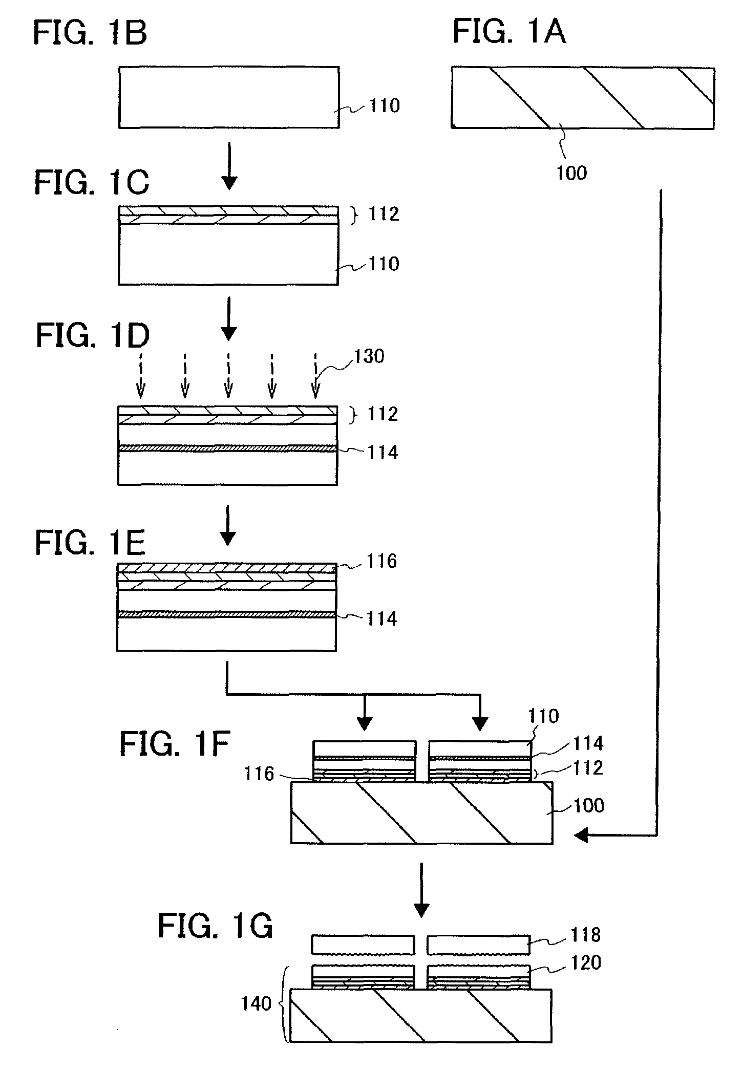
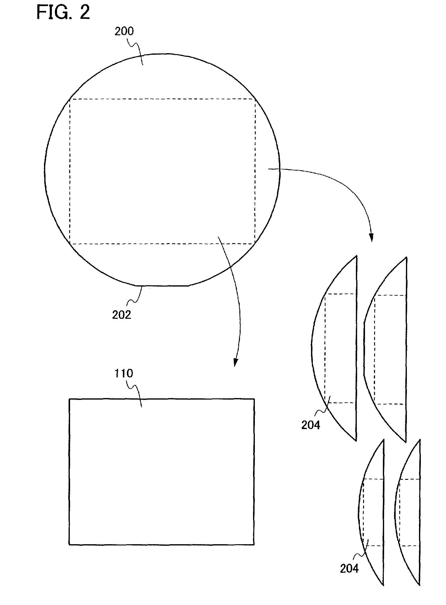
[0051]First, a method for manufacturing a semiconductor substrate (an SOI substrate) used for a semiconductor device is described with reference to FIGS. 1A to 1G, FIG. 2, and FIGS. 3A to 3C.

[0052]First, a base substrate 100 is prepared (see FIG. 1A). As the base substrate 100, a light-transmitting glass substrate used for liquid crystal display devices or the like can be used. As a glass substrate, a substrate having a distortion point of higher than or equal to 580° C. and lower than or equal to 680° C. (preferably, higher than or equal to 600° C. and lower than or equal to 680° C.) may be used; however, the present invention is not limited to the glass substrate. As a material of a glass substrate, for example, a glass material such as aluminosilicate glass, aluminoborosilicate glass, or barium borosilicate glass is used.

[0053]As the base substrate 100, as...

embodiment mode 2

[0177]This embodiment mode describes an example of a method for manufacturing a semiconductor device of the present invention with reference to FIGS. 11A to 11D, FIGS. 12A to 12C, FIGS. 13A to 13C, and FIGS. 14A and 14B. Note that a liquid crystal display device is given as an example of a semiconductor device in this embodiment mode; however, a semiconductor device of the present invention is not limited to the liquid crystal display device.

[0178]First, a semiconductor substrate having a single crystal semiconductor layer, which is manufactured according to the method described in Embodiment Mode 1, is prepared (see FIG. 11A). Here, although a structure in which an insulating layer 1102 including a bonding layer, an insulating layer 1104, and a single crystal semiconductor layer 1106 are provided in this order over a substrate 1100 having an insulating surface (a base substrate) is described, the present invention is not limited thereto. Here, the insulating layer 1104 can be forme...

embodiment mode 3

[0215]This embodiment mode describes a semiconductor device having a light-emitting element according to the present invention (an electroluminescence display device). Note that, since Embodiment Mode 2 can be referred to for the details, the description of a method for manufacturing transistors, which are used for a peripheral circuit region, a pixel region, and the like, is omitted here.

[0216]Note that, in a semiconductor device having a light-emitting element, any one of bottom emission, top emission, and dual emission can be employed. Although this embodiment mode describes a semiconductor device employing bottom emission with reference to FIGS. 15A and 15B, the present invention is not limited thereto.

[0217]The semiconductor device in FIGS. 15A and 15B emits light to the lower side (in the direction of an arrow illustrated in the drawing). Here, FIG. 15A is a plan view illustrating a semiconductor device, and FIG. 15B is a cross-sectional view taken along a line G-H in FIG. 15A...


PUM


Abstract

As a base substrate, a substrate having an insulating surface such as a glass substrate is used. Then, a single crystal semiconductor layer is formed over the base substrate with the use of a large-sized semiconductor substrate. Note that, it is preferable that the base substrate be provided with a plurality of single crystal semiconductor layers. After that, the single crystal semiconductor layers are cut to divide the single crystal semiconductor layers into a plurality of single crystal semiconductor regions by patterning. Next, the single crystal semiconductor regions are irradiated with laser light or heat treatment is performed on the single crystal semiconductor regions in order to improve the planarity of surfaces and reduce defects. Peripheral portions of the single crystal semiconductor regions are not used as semiconductor elements, and central portions of the single crystal semiconductor regions are used as the semiconductor elements.

Description

BACKGROUND OF THE INVENTION[0001]1. Field of the Invention[0002]The present invention relates to a semiconductor device having an SOI (silicon on insulator) structure and a manufacturing method thereof. In this specification, a semiconductor device means any device capable of functioning with the use of semiconductor characteristics.[0003]2. Description of the Related Art[0004]In recent years, LSI technology has been drastically progressed, and an SOI structure by which speeding up and low power consumption are realized has been attracted attention. In this technology, an active region (a channel formation region) of a field effect transistor (FET), which has been conventionally formed of a bulk single crystal silicon, is formed of a single crystal silicon thin film. It is known that a MOS field-effect transistor manufactured using an SOI structure has lower parasitic capacitance than that manufactured using a conventional bulk single crystal silicon substrate, which is an advantage...

Claims


Application Information

Patent Timeline
Patent Type & Authority Patents(United States)
IPC IPC(8): H01L21/302H01L21/322
CPCH01L21/76254H01L27/1266
Inventor YAMAZAKI, SHUNPEIARAI, YASUYUKI
Owner SEMICON ENERGY LAB CO LTD
Learn More