
Polishing pad containing interpenetrating liquified vinyl monomer network with polyurethane matrix therein

a polyurethane matrix and polyurethane matrix technology, applied in the field of polyurethane polishing pads, can solve the problems of incorporated materials, uneven thickness of polyurethane matrix, etc., to achieve stable polishing and stable heat resistance

Active Publication Date: 2010-11-16
RION SMI
View PDF11 Cites 5 Cited by
  • Summary
  • Abstract
  • Description
  • Claims
  • Application Information

AI Technical Summary

Benefits of technology

"The present invention relates to a polyurethane polishing pad with an interpenetrating network structure of vinyl polymer and polyurethane, which has no pores and gas bubbles and is suitable for use in high-speed semiconductor manufacturing processes. The technical effects of this invention include improved polishing performance, uniform dispersion of materials, and increased hardness and elasticity of the pad. Previous polishing pads have incorporated various materials and methods of manufacture, but the present invention provides a new and improved polishing pad that addresses these issues."

Problems solved by technology

The polishing pad utilizing protruded fibers together with voids via incorporation of urethane into polyester felt, as disclosed in U.S. Pat. No. 4,927,432, exhibits superior planarity, but disadvantageously suffers from a slow polishing rate due to low hardness of the pad itself.
IC-series, MH-series and LP-series polishing pads having a surface structure made up of semicircular depressions by incorporation of hollow spherical elements or pores and gas bubbles into polyurethane, commercially available from Rohm and Haas, are currently widely used due to superior polishing rate and planarity, but incorporation of heterogeneous hollow spherical elements or pores / gas bubbles dis-advantageously results in the difficulty of uniform dispersion, thereby leading to a difference in density between the polyurethane matrix and incorporated materials, and the flatness error is gradually increased as the polishing progresses.
The polishing pad having a characteristic surface structure consisting of protrusions and concavities with / without use of filler particles, as disclosed in U.S. Pat. No. 5,209,760, also suffers from difficulty in uniform dispersion of heterogeneous filler particles.
Further, the polishing pad comprising high-pressure gas-containing hollow fine spheres or water soluble polymer powder dispersed in a matrix resin such as polyurethane, as disclosed in Japanese Patent No. 3013105 and Japanese Patent Publication Laid-open No. 2000-71168, disadvantageously suffers from difficulty of dispersion associated with mixing of the water-soluble polymer powder, and decreased hardness of the pad surface as the polishing process progresses, thus resulting in changes in the polishing rate.
However, such a polishing pad suffers from a problem of scratches occurring on the polished surface of a workpiece, and therefore is not widely used at present.
Further, the polishing pad in the non-foam system cannot maintain sufficient amounts of the polishing slurry on the surface of the pad at the time of polishing, and is thus not preferable from the viewpoint of polishing rate.
However, inclusion of pores or gas bubbles in the polyurethane matrix disadvantageously leads to an increase in density difference due to non-uniformity of dispersion, which consequently brings some differences in the polishing performance from lot to lot and also density variation within the corresponding lots from part to part, and an increase in the flatness error as the polishing operation progresses.
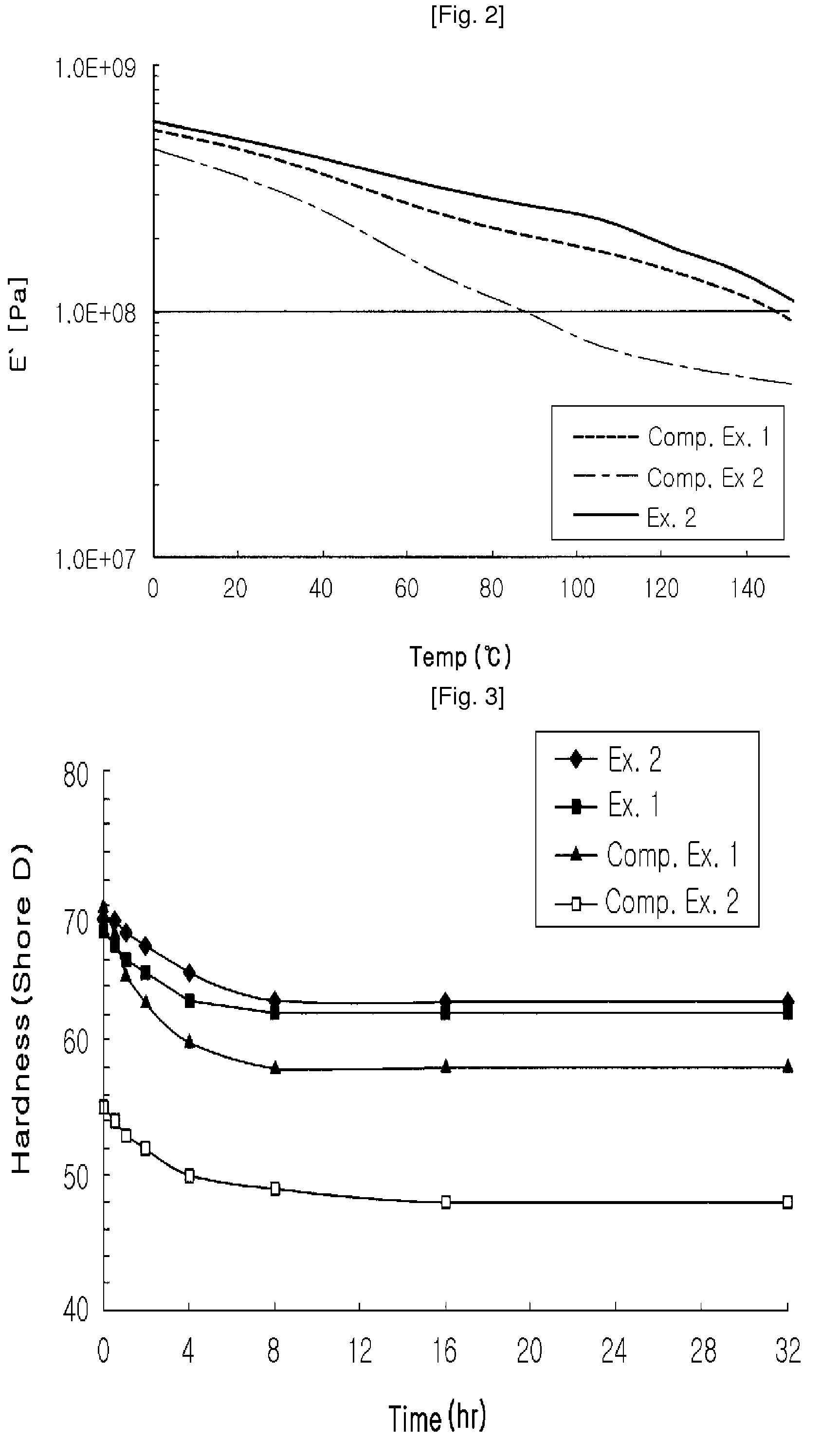
However, these pads have shortcomings in that hardness of the pad is decreased with a further progress of the polishing operation, thereby decreasing the polishing rate, and wearing of the pad leads to the shortened service life of the pad.

Method used


Image

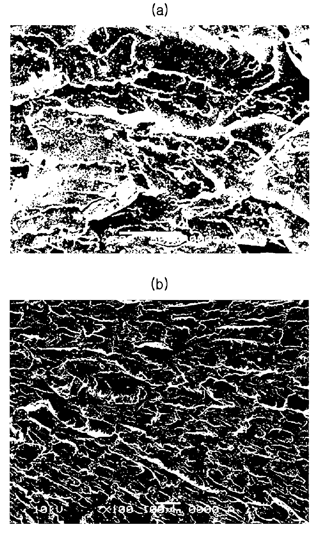
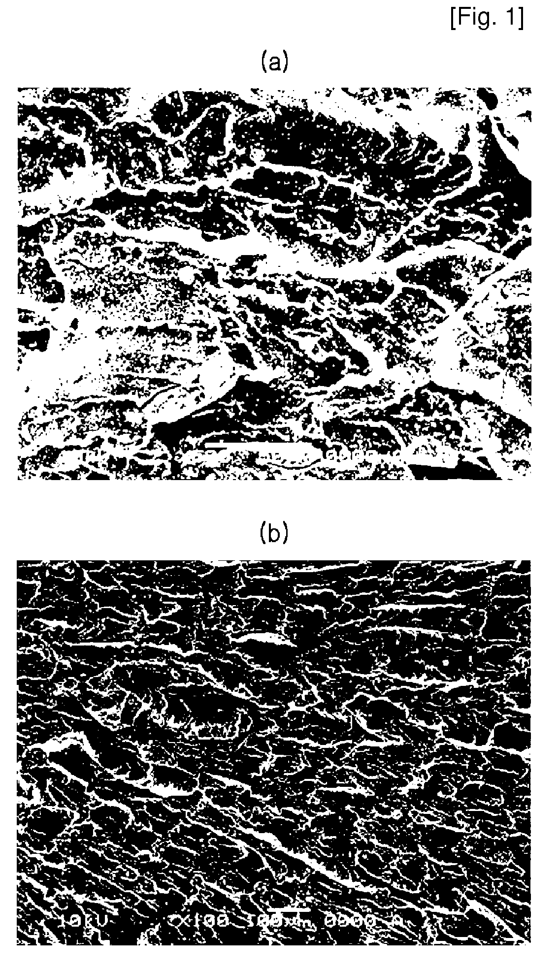
  • Polishing pad containing interpenetrating liquified vinyl monomer network with polyurethane matrix therein
  • Polishing pad containing interpenetrating liquified vinyl monomer network with polyurethane matrix therein
  • Polishing pad containing interpenetrating liquified vinyl monomer network with polyurethane matrix therein

Examples


example 1

[0050]This example is intended to prepare a vinyl oligomer. 0.2% by weight of azobisisobutyronitrile and 44% by weight of a 70:30 mixture of styrene and acrylonitrile were added to a mixing vessel to which 12% by weight of isobutyl alcohol as a chain-transfer solvent was then added. Thereafter, 43.6% by weight of xylene as a chain-transfer solvent and 0.2% by weight of azobisisobutyronitrile as a radical catalyst were added to the reaction vessel.

[0051]Moisture was removed from the reaction vessel to which the mixture of the mixing vessel was then added in a gaseous phase over 2 hours to allow for polymer polymerization. After addition of the mixture was complete, the reactants were aged for 1 hour under the same conditions. After aging of the vinyl monomer was complete, the remaining unreacted styrene and acrylonitrile monomers were removed under reduced pressure.

[0052]The thus-obtained vinyl oligomer is a liquid styrene-acrylonitrile co-oligomer having a molecular weight of less t...

example 2

[0053]100 g of a polyether polyol (functionality=2, and Mw=1000) was charged into a vessel to which 51.2 g of 4,4′-phenylmethane diisocyanate (MDI) was then added. The temperature of the reaction vessel in which two solutions were mixed was elevated to 80° C. and the mixture was reacted with stirring for 3 hours, thereby preparing a prepolymer having isocyanate groups at both ends thereof (Main material #1).

[0054]300 g of 4,4′-methylenebis(o-chloroaniline) was charged into a vessel to which 100 g of a polyether polyol was then added. Herein, the temperature of the mixing vessel was maintained in a range not exceeding 130° C. Then, the defoaming process was carried out with mixing for more than 3 hours to completely remove the remaining gas bubbles from the solution, thereby preparing a curing agent (curing agent #1). The resulting curing agent was mixed with the styrene-acrylonitrile co-oligomer synthesized in Example 1: styrene monomer:acrylonitrile (50 g:50 g:50 g).

[0055]The above...

example 3

[0060]In order to prepare a main material, 100 g of a polyether polyol (functionality=2, and Mw=1000) was charged into a vessel to which 51.2 g of MDI was then added. The reaction vessel in which two solutions were mixed was maintained at 80° C. for 3 hours under stirring, thereby preparing a prepolymer having isocyanate groups at both ends thereof.

[0061]In order to prepare a curing agent, 300 g of 4,4′-methylenebis(o-chloroaniline) was charged into a vessel to which 100 g of a polyether polyol was then added. Herein, the temperature of the mixing vessel was maintained in a range not exceeding 130° C. Thereafter, the defoaming process was carried out with mixing for more than 3 hours to completely remove the remaining gas bubbles from the solution, thereby preparing a curing agent. In this Example, 200 g of a liquid styrene monomer was mixed.

[0062]The above-prepared main material and curing agent were mixed in a urethane reaction equivalent ratio of 1:1 at 80° C. and the resulting m...


PUM

PropertyMeasurementUnit
densityaaaaaaaaaa
half lifeaaaaaaaaaa
temperatureaaaaaaaaaa

Abstract

Provided is a polyurethane polishing pad. More specifically, the present invention provides a polyurethane polishing pad having an interpenetrating network structure of a vinyl polymer with a polyurethane matrix via radical polymerization and having no pores and gas bubbles. The polyurethane polishing pad having an interpenetrating network structure of a vinyl polymer exhibits uniform dispersibility and reduced changes in hardness of the urethane pad due to heat and slurry, thereby resulting in no deterioration of polishing efficiency due to abrasion heat and solubility in the slurry upon polishing, and also enables a high-temperature polishing operation. Further, according to the present invention, the interpenetrating network structure leads to an improved polishing rate and abrasion performance, thereby significantly increasing the service life of the polishing pad.

Description

TECHNICAL FIELD[0001]The present invention relates to a polyurethane polishing pad. More specifically, the present invention relates to a polyurethane polishing pad having an interpenetrating network structure of a vinyl polymer with a polyurethane matrix and having no pores and gas bubbles.BACKGROUND ART[0002]Advancement in technologies has led to demand for high-data processing performance of semiconductor devices, and hence a great deal of research has been directed to development of high-speed semiconductors to cope with such a trend. High-integration of semiconductors is necessary to satisfy high-speed requirements in semiconductors, and consequently the planarization of semiconductor wafer has become an essential factor for the realization of semiconductor integration to a desired level. Such requirements for the realization of high-speed semiconductors have led to incorporation of the polishing process into the semiconductor manufacturing processes. The polishing pad is a con...

Claims


Application Information

Patent Timeline
Patent Type & Authority Patents(United States)
IPC IPC(8): C09K3/14B24D11/00
CPCB24B37/24B24D3/34C08F283/006C08F290/067C08G18/10C08G18/3814C08G18/4825C08J7/123C08G18/6685C08G2270/00C08J2375/04C09K3/14
Inventor PARK, IN-HALEE, JU-YEOLJUN, SUNG-MIN
Owner RION SMI
Learn More