Transverse and/or commutated flux system stator concepts

a technology of transverse and/or commutated flux and stator, which is applied in the direction of propulsion system, magnetic circuit characterised by magnetic materials, and shape/form/construction of magnetic circuits, etc., which can solve the problems of increasing space requirements, increasing complexity, and reducing efficiency,

Active Publication Date: 2010-12-14
ELECTRIC TORQUE MASCH INC
View PDF216 Cites 57 Cited by
  • Summary
  • Abstract
  • Description
  • Claims
  • Application Information

AI Technical Summary

Problems solved by technology

However, many applications require lower rotational speeds.
Gear reduction reduces efficiency, adds complexity, adds weight, and adds space requirements.
Additionally, gear reduction increases system costs and increases mechanical failure rates.
Additionally, if a high rotational speed is not desired, and gear reduction is undesirable, then a motor or alternator typically must have a large number of poles to provide a higher electrical frequency at a lower rotational speed.
However, there is often a practical limit to the number of poles a particular motor or alternator can have, for example due to space limitations.
Moreover, existing multipole windings for alternators and electric motors typically require winding geometry and often complex winding machines in order to meet size and / or power needs.
As the number of poles increases, the winding problem is typically made worse.
Additionally, as pole count increases, coil losses also increase (for example, due to resistive effects in the copper wire or other material comprising the coil).
Prior electric motors, for example conventional DC brushless motors, suffer from various deficiencies.
For example, many electric motors are inefficient at various rotational speeds and / or loads, for example low rotational speeds.
However, high electrical frequency can result in high core losses and hence lower efficiency.
Moreover, high electrical frequency can result in increased cost, increased mechanical complexity, and / or decreased reliability.
Additionally, high electrical frequency and associated losses create heat that may require active cooling, and can limit the operational range of the motor.
Heat can also degrade the life and reliability of a high frequency machine.
Due to the length of the coil windings, resistive effects in the coil lead to coil losses.
For example, such losses convert a portion of electrical energy into heat, reducing efficiency and potentially leading to thermal damage to and / or functional destruction of the motor.
Moreover, many prior electric motors offered low torque densities.
Moreover, such prior electric motors are often quite bulky as a result of the large motor mass.
Often, a motor of sufficient torque and / or power for a particular application is difficult or even impossible to fit in the available area.
Even prior transverse flux machines have been unable to overcome these difficulties.
For example, prior transverse flux machines have suffered from significant flux leakage.
Additionally, using prior transverse flux machines to generate substantial output power often required spinning relatively massive and complicated components (i.e., those involving permanent magnets and / or relatively exotic, dense and / or expensive flux concentrating or conducting materials) at high rates of speed.
Such high-speed operation requires additional expensive and / or complicated components for support and / or system reliability.
Moreover, many prior transverse flux machines are comparatively expensive and / or difficult to manufacture, limiting their viability.
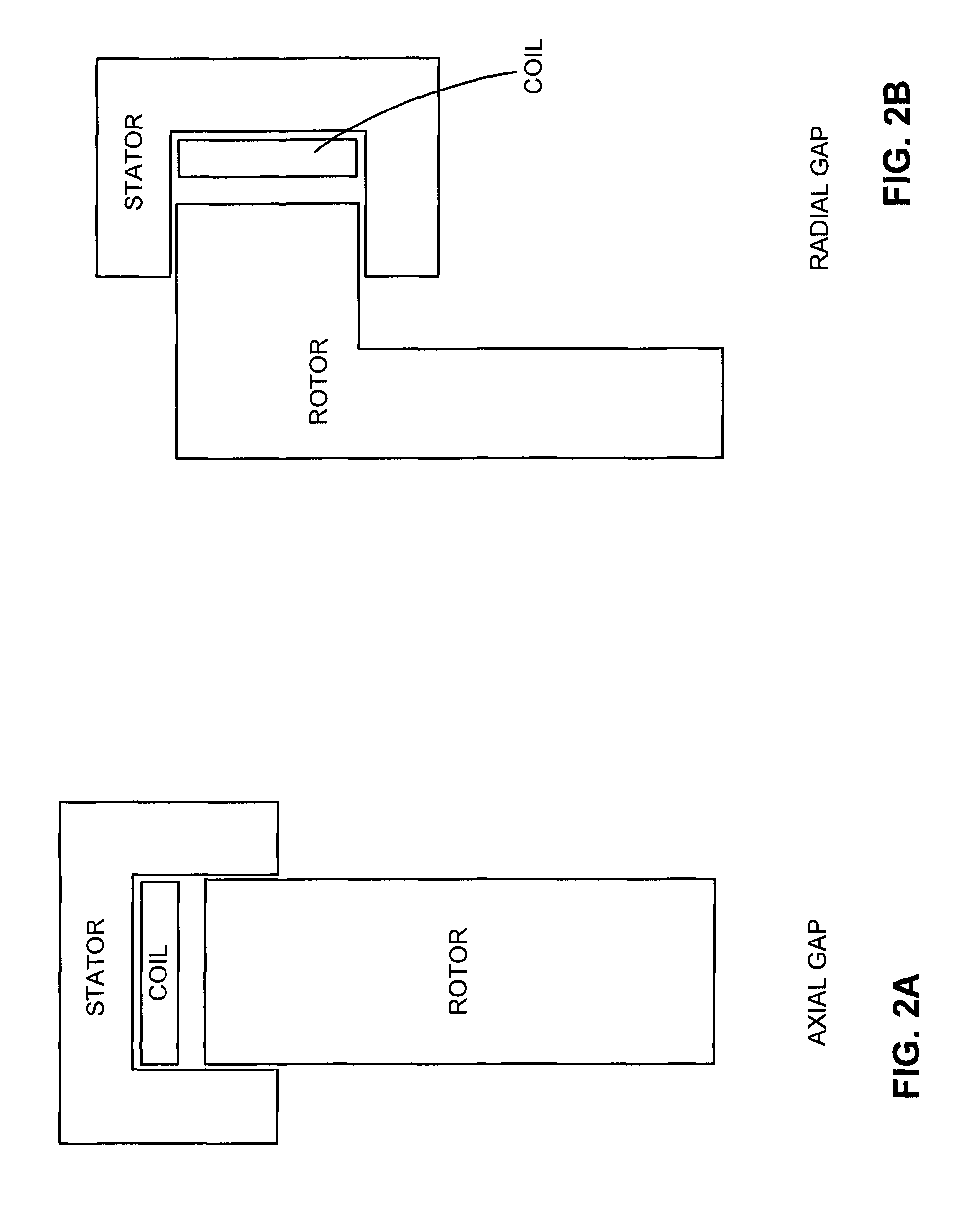
As illustrated, a conventional electric motor typically operates at a comparatively low efficiency at low RPM.
As a result, many conventional electric motors are often desirably operated within an RPM range near peak efficiency.
However, such mechanical components are often costly, bulky, heavy, and / or impose additional energy losses, for example frictional losses.
Such mechanical components can reduce the overall efficiency of the motor / transmission system.
Moreover, a gearbox may be larger and / or weigh more or cost more than the conventional electric motor itself.
Gearboxes also reduce the overall reliability of the system.
Additionally, the efficiency of the transverse and / or commutated flux machine may fall off more slowly past peak efficiency RPM as compared to a conventional electric motor.
However, such techniques typically add significant additional system mass, complexity, bulk, and / or cost.
Additionally, such conventional electric motors configured to produce comparatively high amounts of torque, for example the Siemens 1FW6 motor, are limited to comparatively low RPM operation, for example operation below 250 RPMs.
Minimizing eddy current effects and / or otherwise enhancing flux transmission can be achieved using powdered iron; however, powdered iron generally does not conduct magnetic flux as efficiently as, for example, steel laminate (or other flux conducting material, such as Metglas® 2605SA1) and does not include the physical layer features potentially useful in minimizing or otherwise addressing eddy current and other losses.
In addition, the use of powdered iron has the further drawback of increased hysteresis losses.
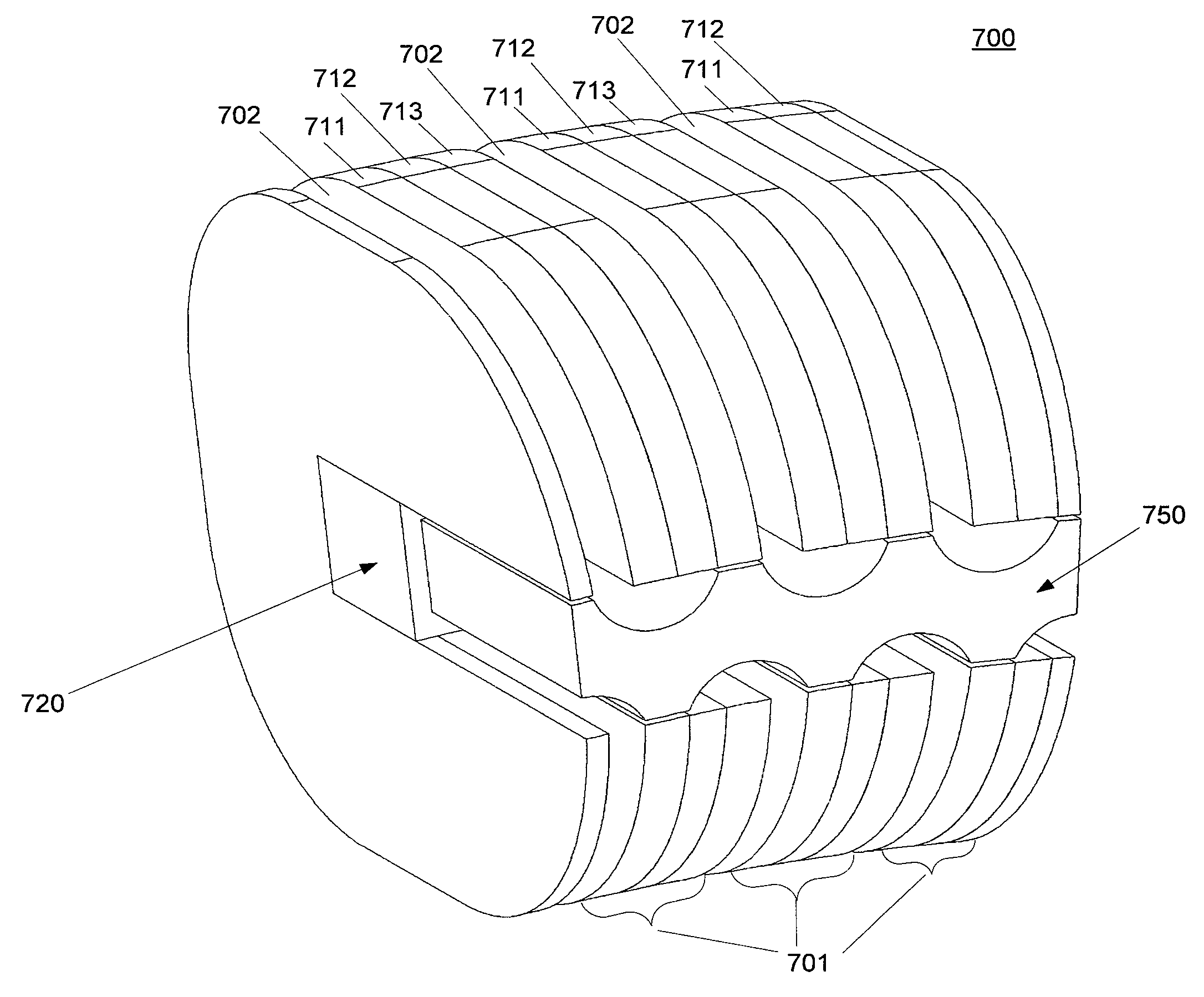
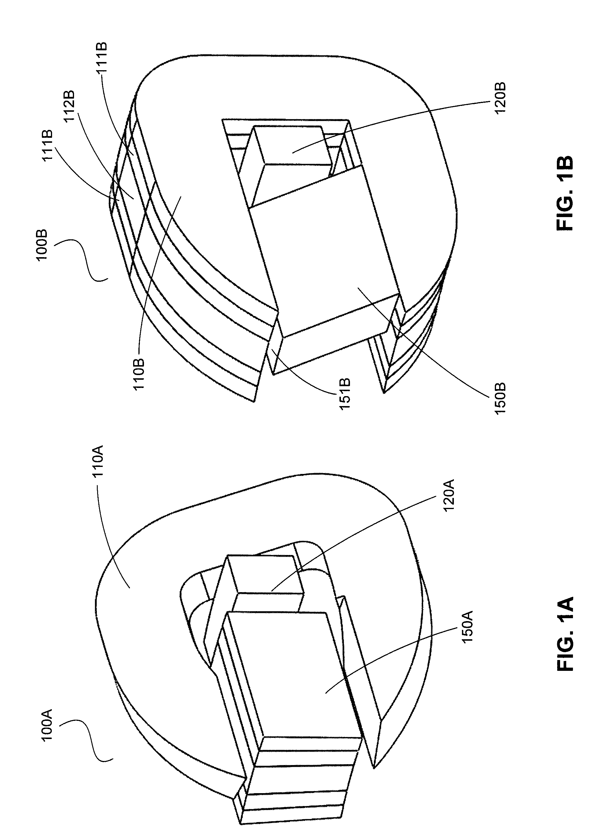
In general, end turns are undesirable because they incur coil losses without doing useful work.
For example, an end turn of a traditional motor incurs large losses as current flows through an end turn coil portion.
Coil losses may include resistive losses, eddy current losses, thermal losses, and / or other coil losses associated with a given coil mass and / or configuration.
Furthermore, heating of the coil due to resistance is also reduced if using less coil material.
Prior systems were often unable to achieve a targeted air gap as the diameter of the rotor increased.
This is generally due to manufacturing tolerances and / or other difficulties, for example the difficulty of producing perfectly round components.
For example, in a vehicle, turning may increase a chance of a rotor and stator scraping, due to the angular momentum of the system.
Moreover, in a vehicle, a rotor and stator may scrape and / or otherwise contact one another in an undesirable manner for various reasons, for example contact with a pothole, lateral acceleration during a turn, an external force, and / or the like.

Method used


Image

  • Transverse and/or commutated flux system stator concepts
  • Transverse and/or commutated flux system stator concepts
  • Transverse and/or commutated flux system stator concepts

Examples


Embodiment Construction

[0033]While exemplary embodiments are described herein in sufficient detail to enable those skilled in the art to practice the invention, it should be understood that other embodiments may be realized and that logical electrical, magnetic, and / or mechanical changes may be made without departing from the spirit and scope of the present disclosure. Thus, the following descriptions are not intended as a limitation on the use or applicability of the present disclosure, but instead, are provided merely to enable a full and complete description of exemplary embodiments.

[0034]For the sake of brevity, conventional techniques for electrical system construction, management, operation, measurement, optimization, and / or control, as well as conventional techniques for magnetic flux utilization, concentration, control, and / or management, may not be described in detail herein. Furthermore, the connecting lines shown in various figures contained herein are intended to represent exemplary functional...


PUM

PropertyMeasurementUnit
diameteraaaaaaaaaa
diameteraaaaaaaaaa
diameteraaaaaaaaaa

Abstract

Disclosed are transverse and / or commutated flux machines and components thereof, and methods of making and using the same. Certain exemplary stators for use in transverse and commutated flux machines may be configured with gaps therebetween, for example in order to counteract tolerance stackup. Other exemplary stators may be configured as partial stators having a limited number of magnets and / or flux concentrators thereon. Partial stators may facilitate ease of assembly and / or use with various rotors. Additionally, exemplary floating stators can allow a transverse and / or commutated flux machine to utilize an air gap independent of the diameter of a rotor. Via use of such exemplary stators, transverse and / or commutated flux machines can achieve improved performance, efficiency, and / or be sized or otherwise configured for various applications.

Description

CROSS REFERENCE TO RELATED APPLICATIONS[0001]This application is a non-provisional of U.S. Provisional No. 61 / 110,874 filed on Nov. 3, 2008 and entitled “ELECTRICAL OUTPUT GENERATING AND DRIVEN ELECTRICAL DEVICES USING COMMUTATED FLUX AND METHODS OF MAKING AND USE THEREOF INCLUDING DEVICES WITH TRUNCATED STATOR PORTIONS.”[0002]This application is also a non-provisional of U.S. Provisional No. 61 / 110,879 filed on Nov. 3, 2008 and entitled “ELECTRICAL OUTPUT GENERATING AND DRIVEN ELECTRICAL DEVICES USING COMMUTATED FLUX AND METHODS OF MAKING AND USE THEREOF.”[0003]This application is also a non-provisional of U.S. Provisional No. 61 / 110,884 filed on Nov. 3, 2008 and entitled “METHODS OF MACHINING AND USING AMORPHOUS METALS OR OTHER MAGNETICALLY CONDUCTIVE MATERIALS INCLUDING TAPE WOUND TORROID MATERIAL FOR VARIOUS ELECTROMAGNETIC APPLICATIONS.”[0004]This application is also a non-provisional of U.S. Provisional No. 61 / 110,889 filed on Nov. 3, 2008 and entitled “MULTI-PHASE ELECTRICAL ...

Claims


Application Information

Patent Timeline
Patent Type & Authority Patents(United States)
IPC IPC(8): H02K1/06
CPCH02K1/246H02K41/025H02K37/02H02K1/02H02K1/04Y10T29/49012H02K2201/12H02K2201/15H02K21/26
Inventor CALLEY, DAVID G.JANECEK, THOMAS F.
Owner ELECTRIC TORQUE MASCH INC
Why Eureka
Try Eureka