Motor drive device, method, and cooling device using the same
a technology of motor drive and cooling device, which is applied in the direction of electronic commutators, pulse techniques, dynamo-electric converter control, etc., can solve the problems of large noise, large voltage applied to transistors, and rapid change of time waveform of regenerative current flowing through freewheel diodes, so as to reduce noise generated by fan motors and reduce circuit area , the effect of reducing the noise of electronic devices
- Summary
- Abstract
- Description
- Claims
- Application Information
AI Technical Summary
Benefits of technology
Problems solved by technology
Method used
Image
Examples
first embodiment
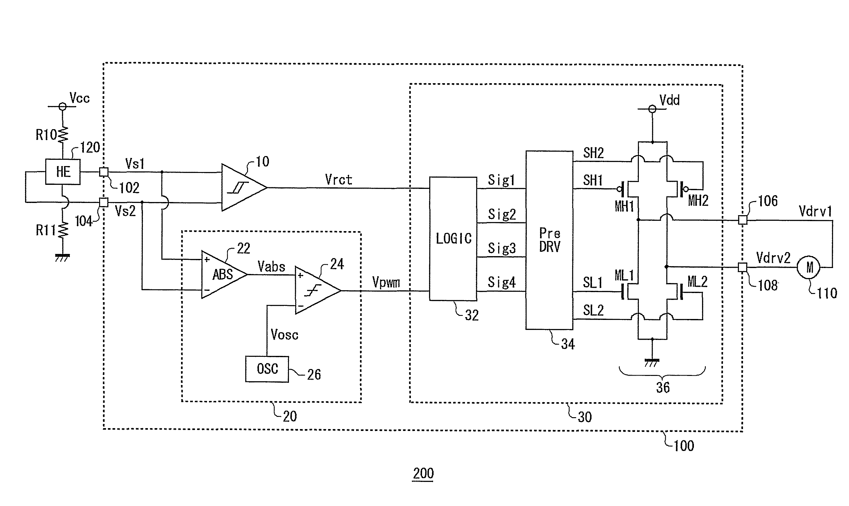
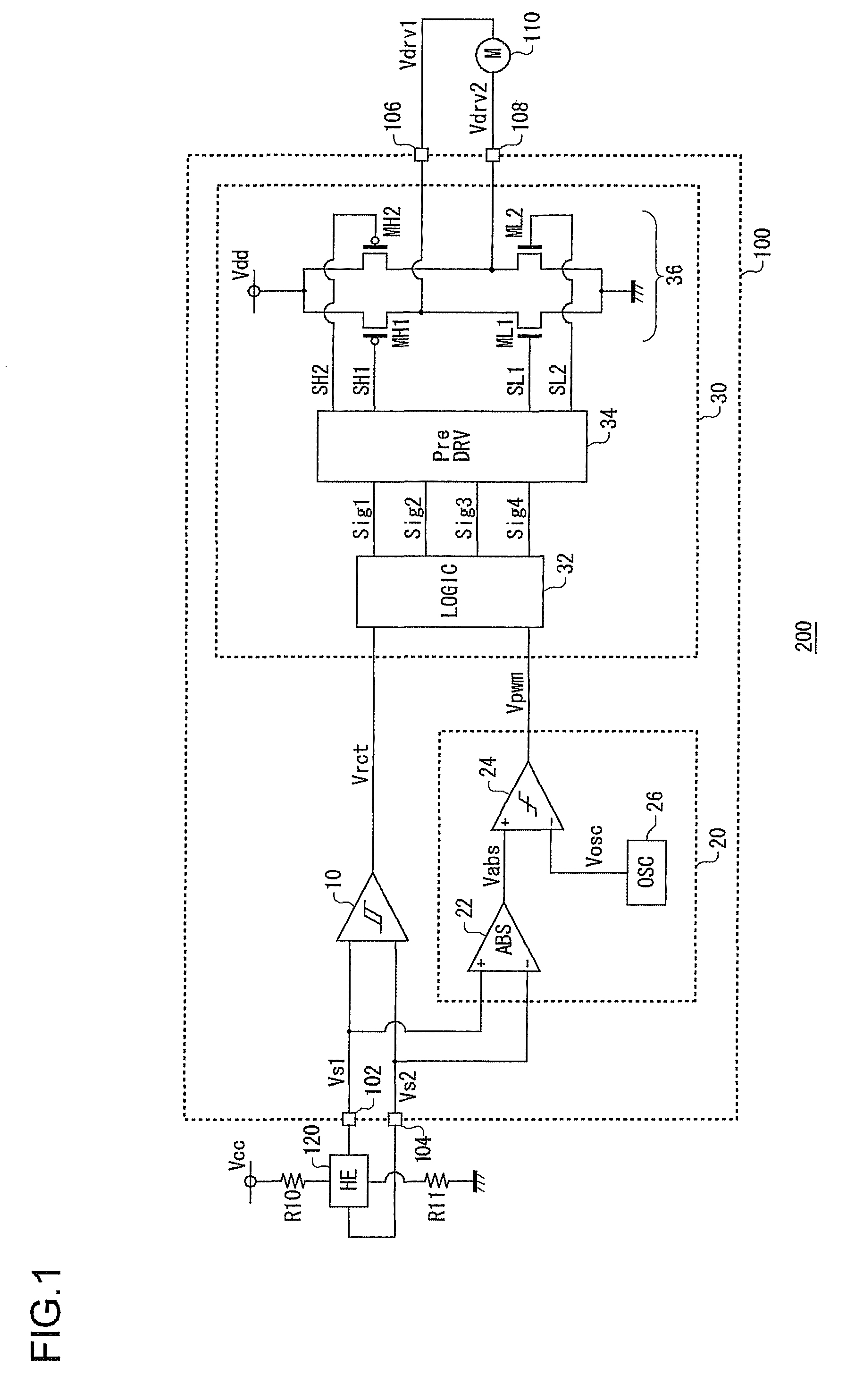
[0034]In an embodiment of the invention, an explanation is given concerning a motor drive apparatus used in a cooling system for cooling an electronic device such as a refrigerator, a personal computer, or the like. FIG. 1 is a circuit diagram showing a configuration of the cooling system 200 according to a first embodiment of the invention. The cooling system 200 includes a motor drive apparatus 100, a fan motor 110, and a Hall element 120.
[0035]The fan motor 110 is a single-phase full-wave motor, and is disposed opposite an object that is to be cooled, which is not shown in the figure. In the fan motor 110, a coil current, that is, an energization state, is controlled by a drive voltage outputted from the motor drive apparatus 100, and rotation is controlled.
[0036]The Hall element 120 is connected to a power supply line, to which a power supply voltage Vcc is applied via a resistor R10, and is grounded via a resistor R11. The size of a signal outputted from the Hall element 120 is...
second embodiment
[0060]In the first embodiment, an explanation was given concerning cases in which a single phase motor is driven linearly, for the energization time-period; in a second embodiment as below, however, an explanation is given concerning cases in which a single phase motor is driven by switching. FIG. 3 is a circuit diagram showing a configuration of a cooling system 200 according to the second embodiment. In FIG. 3, component elements that are identical or equivalent to component elements in the configuration of FIG. 1 are given the same reference symbols, and repeated explanations are omitted as appropriate.
[0061]A temperature detection circuit 130, which generates a temperature detection voltage Vth that is dependent on surrounding temperature of an object to be cooled, is connected to an external portion of the motor drive apparatus 100. The temperature detection circuit 130 includes a thermistor Rth and a resistor R12 connected in series between a reference voltage and ground. Volt...
third embodiment
[0065]In a third embodiment, an explanation is given concerning a cooling system 200 that controls a fan motor 110 based not on temperature, but on a pulse width modulated control signal Vcnt which controls the rotational frequency of a fan motor 110 that is to be driven. In the present embodiment, a motor drive apparatus 100 has a configuration similar to FIG. 3, and is provided with a smoothing circuit 140, instead of the temperature detection circuit 130. FIG. 4 is a circuit diagram showing a configuration of the smoothing circuit 140 of the cooling system 200 according to the third embodiment.
[0066]The smoothing circuit 140 smoothes the pulse width modulated control signal Vcnt which controls the rotational frequency of the fan motor 110, and outputs a result thereof as a direct current rotation control voltage Vcnt′.
[0067]The smoothing circuit 140 includes a transistor Q1, a capacitor C1, and a resistor R14. The control signal Vcnt is inputted to a base of the transistor Q1, an...
PUM
 Abstract
Description
Claims
Application Information
 - R&D
- Intellectual Property
- Life Sciences
- Materials
- Tech Scout
- Unparalleled Data Quality
- Higher Quality Content
- 60% Fewer Hallucinations
Browse by: Latest US Patents, China's latest patents, Technical Efficacy Thesaurus, Application Domain, Technology Topic, Popular Technical Reports.
© 2025 PatSnap. All rights reserved.Legal|Privacy policy|Modern Slavery Act Transparency Statement|Sitemap|About US| Contact US: help@patsnap.com


