Super abrasive grain wire saw winding structure, super abrasive grain wire saw cutting device, and super abrasive grain wire saw winding method

a super abrasive wire saw and cutting device technology, applied in the direction of metal sawing devices, saw chains, manufacturing tools, etc., can solve problems such as unreeled smoothly, and achieve the effects of preventing the engagement of superabrasive wire saws, reducing the damage to the bonding material and the falling of superabrasive grains, and preventing the friction between superabrasive wire saws

Inactive Publication Date: 2011-04-19
ALLIED MATERIAL
View PDF48 Cites 36 Cited by
  • Summary
  • Abstract
  • Description
  • Claims
  • Application Information

AI Technical Summary

Benefits of technology

[0010]An object of the present invention is to solve the problems above, and provide a superabrasive wire saw-wound structure, a cutting device with a superabrasive wire saw, and a method of winding a superabrasive wire saw which can reduce damage to a bonding material and falling of superabrasive grains.

Problems solved by technology

In addition, Japanese Patent Laying-Open No. 4-351222 discloses a bonding wire winding which is wound reciprocatingly to be multi-layered such that it is unreeled smoothly during a bonding operation.

Method used


Image

  • Super abrasive grain wire saw winding structure, super abrasive grain wire saw cutting device, and super abrasive grain wire saw winding method
  • Super abrasive grain wire saw winding structure, super abrasive grain wire saw cutting device, and super abrasive grain wire saw winding method
  • Super abrasive grain wire saw winding structure, super abrasive grain wire saw cutting device, and super abrasive grain wire saw winding method

Examples


first embodiment

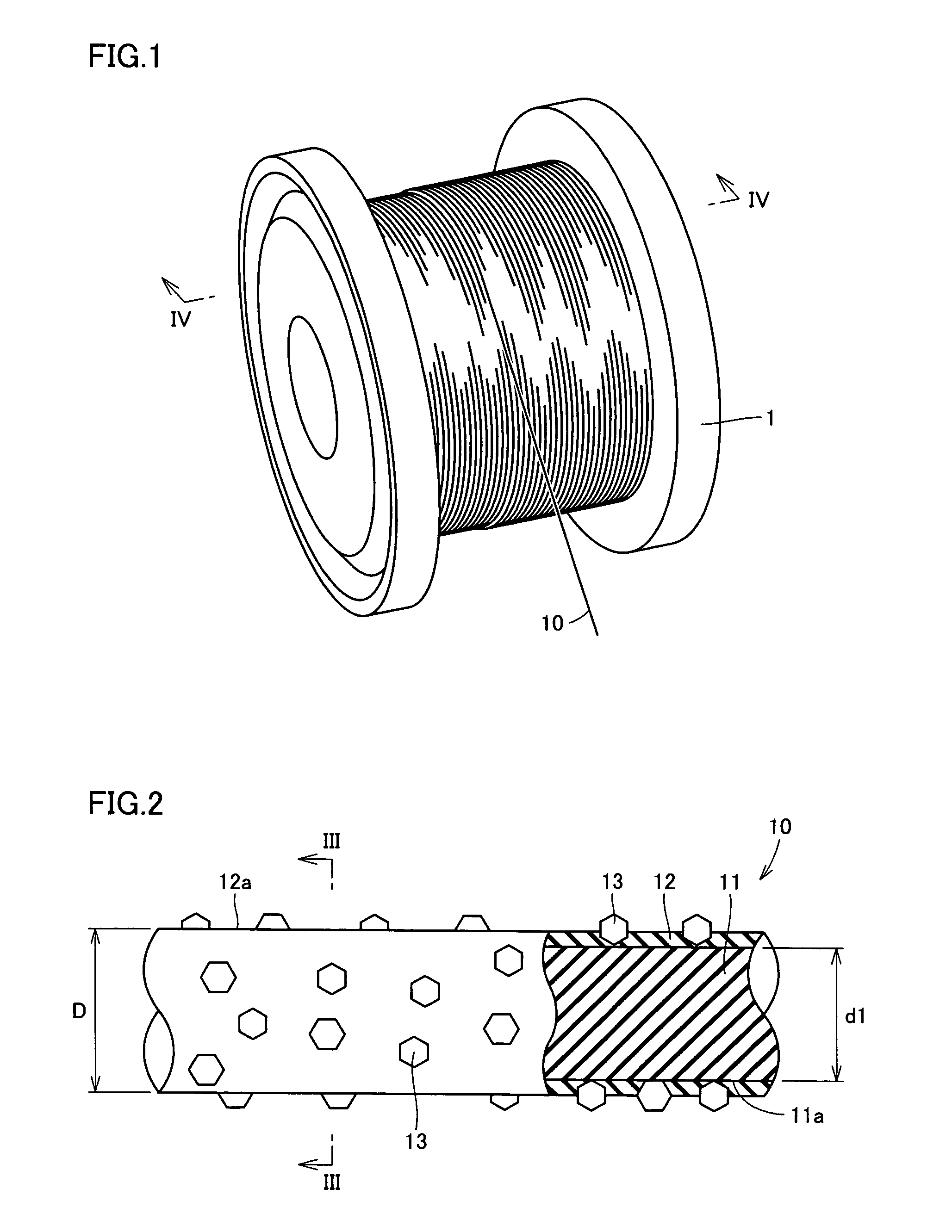
[0030]Referring to FIG. 1, a superabrasive wire saw 10 is wound around a peripheral surface of a reel 1 shaped like a cylinder to be multi-layered. As described in detail below, in the superabrasive wire saw-wound structure in the present embodiment, a pitch P with which superabrasive wire saw 10 is wound around the peripheral surface is set within a predetermined range.

[0031]Superabrasive wire saw 10 is used for slicing a silicon ingot into silicon wafers, and performing a cutting process on cemented carbide, cermet, ceramics, germanium, ferrite, Sendust, alnico, samarium cobalt, neodymium magnet, glass, rock crystal, sapphire, stone material, firebrick, tile, resin material, fiber-glass reinforced plastic (FRP), carbon fiber reinforced plastic (CFRP), graphite, grindstone, precious stone, metallic material, and others.

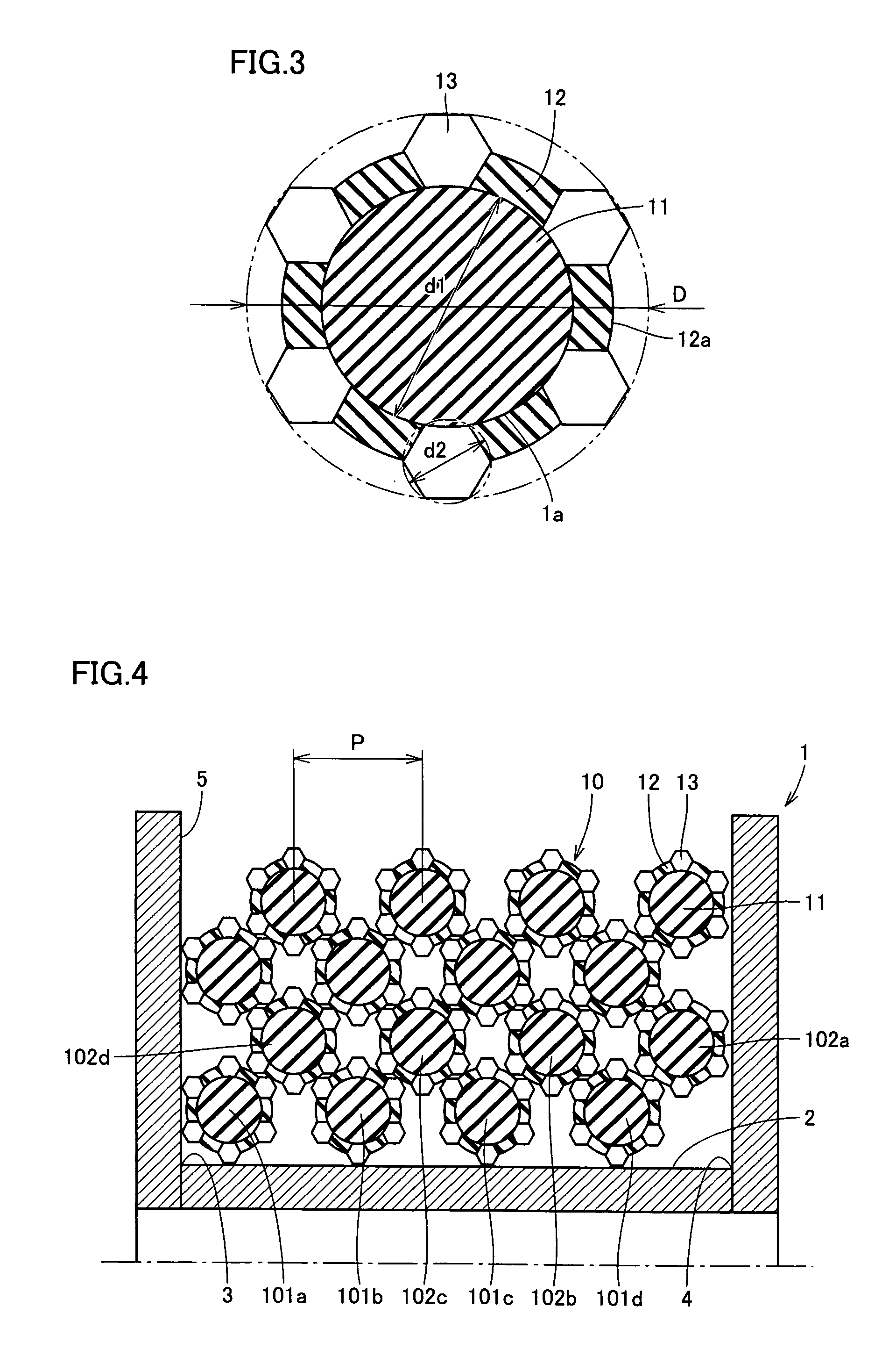
[0032]A part of FIG. 2 shows a longitudinal cross section of the superabrasive wire saw. Referring to FIGS. 2 and 3, superabrasive wire saw 10 includes a core wire 1...

second embodiment

[0051]A superabrasive wire saw-wound structure according to the second embodiment of the present invention basically has a structure similar to that of the first embodiment. The description of the overlapping structure thereof will not be repeated herein.

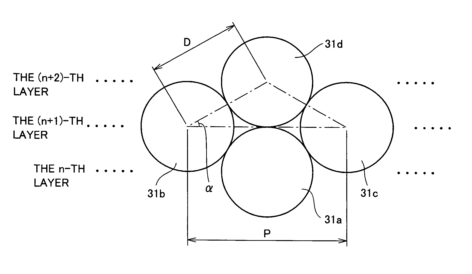
[0052]According to the present embodiment, superabrasive wire saw 10 is wound around peripheral surface 2 of reel 1 with pitch P further satisfying a relation of 1.1D1 / 2) D. More preferably, pitch P satisfies a relation of 1.2D1 / 2) D. With the superabrasive wire saw-wound structure configured as such, the effects which will be described below can be obtained in addition to the effects of the first embodiment.

[0053]Referring to FIG. 6, over a superabrasive wire saw 31a wound in an n-th layer, a superabrasive wire saws 31b and 31c are wound in an (n+1)-th layer and a superabrasive wire saw 31d is wound in an (n+2)-th layer. These superabrasive wire saws are wound with pitch P satisfying a relation of P=(31 / 2) D.

[0054]In this case, the...

third embodiment

[0056]Referring to FIG. 7, a cutting device with a superabrasive wire saw 51 (hereinafter referred to “cutting device 51”) includes a superabrasive wire saw supplier 57 reeling and unreeling superabrasive wire saw 10 to and from a workpiece 55. Superabrasive wire saw supplier 57 is provided with reel 1 having superabrasive wire saw 10 wound by using the superabrasive wire saw-wound structure according to the first or second embodiment. Two reels 1 are placed on respective lateral sides with respect to workpiece 55 and mounted on the rotating shafts of the motors, respectively.

[0057]Cutting device 51 further includes a plurality of guide rollers 52 and 53 guiding superabrasive wire saw 10, two main rollers 56 placed under workpiece 55 at a predetermined spacing, and two cutting fluid nozzles 54 provided in the vicinity of main rollers 56, respectively. Grooves are provided on a peripheral surface of main roller 56 according to a cutting size of workpiece 55. Superabrasive wire saw 10...


PUM

PropertyMeasurementUnit
angleaaaaaaaaaa
diameter d1aaaaaaaaaa
diameteraaaaaaaaaa

Abstract

A superabrasive wire saw-wound structure includes a superabrasive wire saw (10) formed with an average diameter D and a reel (1). The superabrasive wire saw (10) includes a core wire (11), a bonding material (12) surrounding a surface of the core wire (11), and a plurality of superabrasive grains (13) bonded to the surface of the core wire (11) with the bonding material (12). The reel (1) includes a peripheral surface (2) having one end (3) and the other end (4). The superabrasive wire saw (10) which is to be unreeled successively toward a workpiece is wound around the peripheral surface (2) reciprocatingly between the one end (3) and the other end (4) to be multi-layered. A pitch P for winding the superabrasive wire saw (10) around the peripheral surface (2) between the one end (3) and the other end (4) satisfies a relation of D<P<2D. According to the present invention, there can be provided a superabrasive wire saw-wound structure, a cutting device with a superabrasive wire saw, and a method of winding a superabrasive wire saw which can reduce damage to a bonding material and falling of a superabrasive grain.

Description

TECHNICAL FIELD[0001]The present invention generally relates to a superabrasive wire saw-wound structure, a cutting device with a superabrasive wire saw, and a method of winding a superabrasive wire saw, and more particularly, to a bonded-abrasive type superabrasive wire saw-wound structure, a cutting device with a superabrasive wire saw, and a method of winding a superabrasive wire saw which are used for slicing a silicon ingot into silicon wafers, and performing a cutting process on various materials such as metal, resin, ore, glass, sapphire, rock crystal, SiC, and compound semiconductor.BACKGROUND ART[0002]Conventionally, a bonded-abrasive type diamond wire saw, which has diamond abrasive grains bonded to the surface of a core wire, has been proposed as an example of a superabrasive wire saw. With the diamond wire saw, a material such as a metal can be cut extremely cleanly. In addition, there is no need for a slurry having an abrasive fluid and abrasive grains blended; instead,...

Claims


Application Information

Patent Timeline
Patent Type & Authority Patents(United States)
IPC IPC(8): B28D1/06B28D1/08B24B7/00B26D5/20B24B9/00B23D57/00B23D61/18B24B27/06B65H54/28
CPCB23D57/0061B65H54/2872B24B27/0633B23D61/185Y10T83/9292B24B27/06B65H54/28
Inventor NAKAI, MASANORIYAMANAKA, MASAAKIISHITOBI, YOSHIZUMI
Owner ALLIED MATERIAL
Why Eureka
Try Eureka