Methods and systems for realizing high resolution three-dimensional optical imaging

a three-dimensional, high-resolution technology, applied in the field of signal processing, can solve the problems of large amount of data processing, test object limits the 3-d resolution of the imager, image blurring, etc., and achieve the effect of reducing the detection dynamic rang

Inactive Publication Date: 2011-07-12
UNIV OF CENT FLORIDA RES FOUND INC
View PDF13 Cites 50 Cited by
  • Summary
  • Abstract
  • Description
  • Claims
  • Application Information

AI Technical Summary

Benefits of technology

[0029]An eighth objective of the invention is to provide methods and systems for an instrument that can take data on a per wavelength basis across a specified band. In effect, it becomes a spectroscopy tool including for spectral imaging. This per wavelength magnitude and phase RF data collected from the optical test sam...

Problems solved by technology

In general, the wave properties of the probing signal in combination with the material properties of the test object limits the 3-D resolution of the imager.
Images can get blurred due to fast motion of objects and/or because the image is out of focus because of imperfect imaging conditions.
In effect, using these computer algorithms as is done today, massive amount of data processing is required.
Compared to electron microscopy where special sample preparation is required, optical techniques are particularly non-invasive when live tissue cannot be prepared due to material distortions arising from certain treatments.
The strength of this system comes from its in-line interferometric design coupled with heterodyne optical detection a...

Method used


Image

  • Methods and systems for realizing high resolution three-dimensional optical imaging
  • Methods and systems for realizing high resolution three-dimensional optical imaging
  • Methods and systems for realizing high resolution three-dimensional optical imaging

Examples


Embodiment Construction

[0049]Before explaining the disclosed embodiments of the present invention in detail it is to be understood that the invention is not limited in its application to the details of the particular arrangements shown since the invention is capable of other embodiments. Also, the terminology used herein is for the purpose of description and not of limitation.

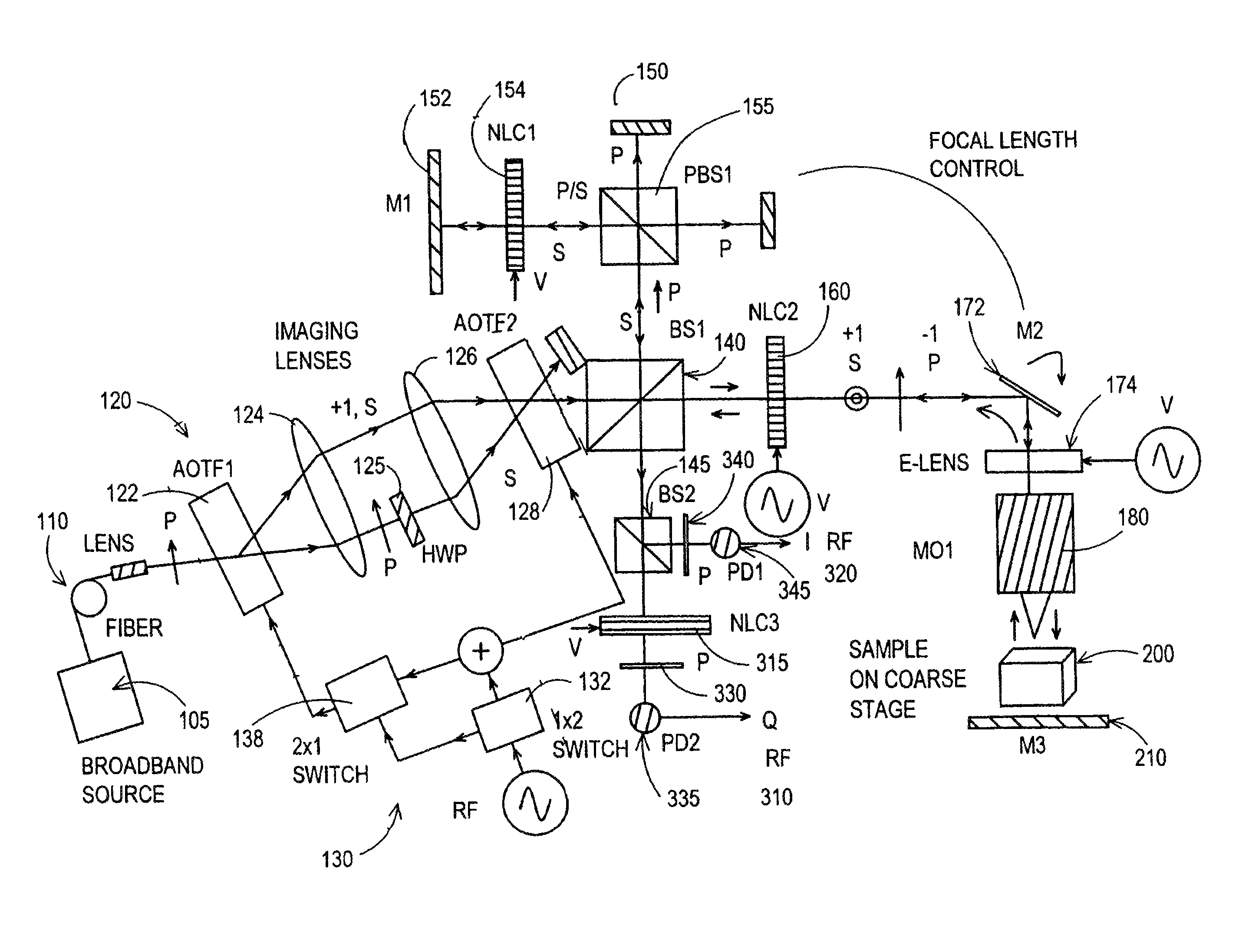
[0050]Earlier methods and systems proposed agile confocal microscopy for profilometry and 3-D imaging. The methods, systems and instruments of the present inventions key concept for agile confocal microscopy is to deploy electronically controlled 3-dimensional beam forming optics to steer a light beam in a confocal microscope as described in U.S. Pat. No. 6,687,036 issued Feb. 3, 2004 issued to N. A. Riza a co-inventor of the present invention and assigned to the same assignee which is incorporated herein by reference titled Multiplexed Optical Scanner Technology” and described by the inventor in N. A. Riza and A. Bokhari, “Agile Opt...


PUM


Abstract

Methods and systems for realizing high resolution three-dimensional (3-D) optical imaging using diffraction limited low resolution optical signals. Using axial shift-based signal processing via computer based computation algorithm, three sets of high resolution optical data are determined along the axial (or light beam propagation) direction using low resolution axial data. The three sets of low resolution data are generated by illuminating the 3-D object under observation along its three independent and orthogonal look directions (i.e., x, y, and z) or by physically rotating the object by 90 degrees and also flipping the object by 90 degrees. The three sets of high resolution axial data is combined using a unique mathematical function to interpolate a 3-D image of the test object that is of much higher resolution than the diffraction limited direct measurement 3-D resolution. Confocal microscopy or optical coherence tomography (OCT) are example methods to obtain the axial scan data sets.

Description

[0001]This application claims the benefit of priority to U.S. Provisional Patent Application No. 61 / 153,444 filed on Feb. 18, 2009.FIELD OF THE INVENTION[0002]This invention relates to signal processing and, in particular, to methods and systems for a multi-function optical microscope using signal processing for realizing high resolution three dimensional optical imaging using diffraction limited low resolution optical signals.BACKGROUND AND PRIOR ART[0003]There are numerous applications where 3-D imaging of objects is desirable. Applications include the electromagnetic (EM) spectrum to ultrasonic frequencies. Instruments for example include Radio Frequency (RF) radar, optical radar, X-ray imagers, optical microscopes, and ultrasound. In general, the wave properties of the probing signal in combination with the material properties of the test object limits the 3-D resolution of the imager. In classical wave optics (EM radiation), wave diffraction sets a limit on the smallest size th...

Claims


Application Information

Patent Timeline
IPC IPC(8): G01B11/22
CPCG01B11/24G02B21/0068G02B21/0072
Inventor RIZA, NABEEL A.
Owner UNIV OF CENT FLORIDA RES FOUND INC
Why Eureka
Try Eureka