
Grease, rolling bearing, constant velocity joint, and rolling parts

a technology of constant velocity joint and grease, which is applied in the field of grease, can solve the problems of increasing heat generation and frictional wear, reducing disadvantage, and prone to fracture of the lubricating film of the lubricating grease, so as to prevent the occurrence of flaking, improve the resistance to heat and durability, and prevent the effect of frictional wear on the lubricating surfa

Inactive Publication Date: 2011-08-23
NTN CORP
View PDF49 Cites 13 Cited by
  • Summary
  • Abstract
  • Description
  • Claims
  • Application Information

AI Technical Summary

Benefits of technology

The bismuth-based grease significantly reduces frictional wear and heat generation, providing long-term durability and maintaining extreme-pressure properties, suitable for high-load and high-speed applications in rolling stocks, building machines, and automotive components.

Problems solved by technology

Heretofore, when the rolling bearing in which grease is enclosed is used in a high load-applied condition, a lubricating film of lubricating grease is liable to fracture.
When the lubricating film fractures, metal contact occurs to generate a disadvantage that heat generation and frictional wear increase.
Therefore by using grease containing an extreme-pressure agent (EP agent), the disadvantage is decreased.
Thus at the flange portion, the fracture of the lubricating oil film is liable to occur.
Thus there is a problem that when water penetrates into the bearing, a lubricating oil film is fractured and the bearing is damaged at an early stage owing to inferior lubrication.
Thus in an environment in which the rolling roller is frequently mounted and removed for re-grinding, the seal lip portion is much damaged.
Consequently rolling water and cooling water penetrate into the bearing at a rate of not more than 20% of the grease and mix with a lubricant (normally, grease lubricant in which lithium-based thickener such as Adlex, Albania or the like is used), thus deteriorating the lubricating function thereof and causing the bearing to be damaged in an early stage owing to inferior lubrication.
It cannot be said that the constant velocity joint is satisfactory in a severe operation condition generated in recent high-performance cars.
Thus a flaking phenomenon is liable to occur owing to metal fatigue.
Consequently the conventional grease is incapable of sufficiently preventing the occurrence of the flaking phenomenon.
Thus the lubricating oil film of the lubricating grease is liable to fracture.
Owing to the fracture of the lubricating oil film, metal contact occurs to generate a disadvantage that heat generation and frictional wear increase.
Thus by using the extreme-pressure agent-containing grease, its disadvantage is decreased.
Because the sliding friction is larger than the rolling friction, seizing of the flange portion is liable to occur when the use condition becomes severe.
Therefore the conventional rolling bearing and the conventional constant velocity joint have a problem respectively that they cause a grease-exchanging work to be frequently performed and are incapable of making maintenance free.
Further as the use condition of the rolling bearing and that the constant velocity joint become severe, for example, when they are lubricated at a high speed of not less than 100,000 in dN value, the conventional grease is incapable of preventing the occurrence of the flaking phenomenon sufficiently.
Thus it is difficult to use the constant velocity joint.
In the case of the conventional rolling parts and the rolling bearing, when the grease-enclosed rolling bearing is used under a high load, the lubricating oil film of the lubricating grease is liable to fracture.
When the lubricating oil film has fractured, metal contact occurs to generate a disadvantage that heat generation and frictional wear increase.
But these rolling parts have a problem that they are insufficient in wear-decreasing effect on sliding surfaces thereof and lack long-term durability in the use condition of a high temperature and a high speed.
Thus the grease-enclosed rolling bearing has a problem that at the flange portion, the fracture of the lubricating oil film is liable to occur.

Method used


Image

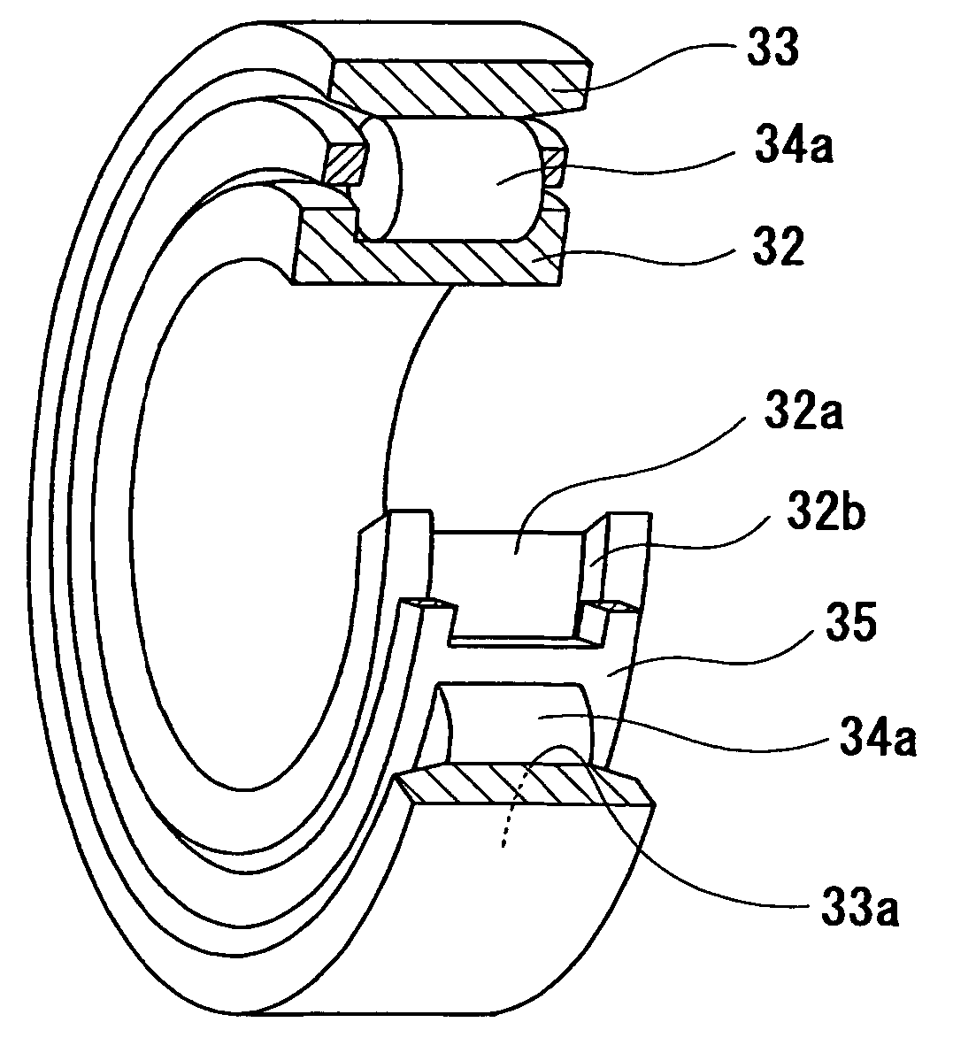
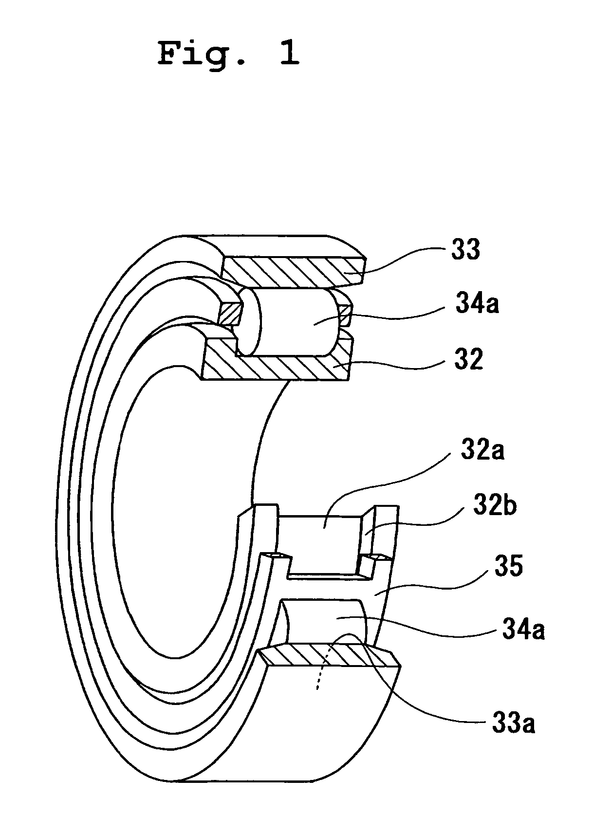
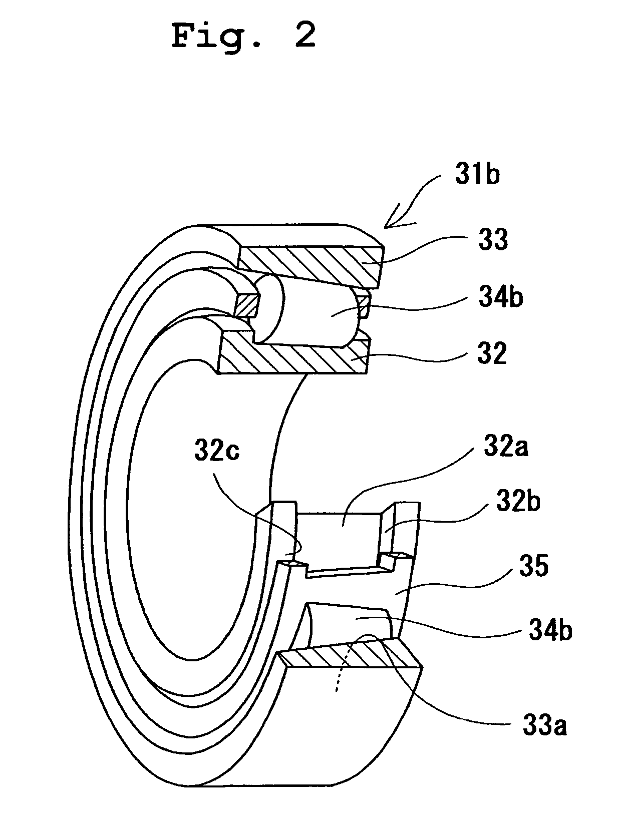
  • Grease, rolling bearing, constant velocity joint, and rolling parts
  • Grease, rolling bearing, constant velocity joint, and rolling parts
  • Grease, rolling bearing, constant velocity joint, and rolling parts

Examples


examples 1 through 11

[0265]In a reaction container, as shown in table 1, a thickener was added to base oil, and uniformalizing treatment was performed by using a triple roll mill to obtain lithium soap / mineral oil-based grease (viscosity of base oil at 40° C.: 100 mm2 / s, mixing consistency: 220), urea / PAO oil-based grease (viscosity of base oil at 40° C.: 46 mm2 / s, mixing consistency: 280), lithium soap / ester oil-based grease (viscosity of base oil at 40° C.: 33 mm2 / s, mixing consistency: 250), and urea / ether oil-based grease (viscosity of base oil at 40° C.: 100 mm2 / s, mixing consistency: 300).

[0266]Further, as an extreme-pressure agent, bismuth or inorganic bismuth was added to the above-described grease at rates shown in table 1 to form grease of each example. On the obtained grease, an extreme-pressure property evaluation test and a test of a roller bearing were conducted. Results are shown in table 1.

example 12

[0284]A copper plate (SUJ2, thickness: 10 mm) and a ring-shaped specimen (SUJ2) of φ40 mm×thickness of 10 mm were immersed in a solution containing 5 g of the bismuth trioxide (produced by Wako Pure Chemical Industries, Ltd.) and 95 g of PAO oil (SYNFLUID 801 produced by Nippon Steel Chemical Co., Ltd.) to which the bismuth trioxide was added. The ring-shaped specimen was rotated at 2000 rpm for 20 hours with an end surface of the ring-shaped specimen pressed against the copper plate at a load of 490 N. By frictional heat generated at that time, a coating film of the bismuth trioxide was formed on the end surface of the ring-shaped specimen. The formation of the coating film of the bismuth trioxide on the end surface of the ring-shaped specimen was confirmed by surface analysis performed by means of Photoemission Spectroscopy (hereinafter referred to as XPS).

[0285]By using two ring-shaped specimens, an extreme-pressure property evaluation test shown below was conducted. Results are ...

example 13

[0286]The copper plate (SUJ2, thickness: 10 mm) and the ring-shaped specimen (SUJ2) of φ40 mm×thickness: 10 mm were immersed in a solution containing 5 g of bismuth (produced by Wako Pure Chemical Industries, Ltd.)and 95 g of the PAO oil (SYNFLUID 801 produced by Nippon Steel Chemical Co., Ltd.) to which the bismuth was added. The ring-shaped specimen was rotated at 2000 rpm for 20 hours with the end surface of the ring-shaped specimen pressed against the copper plate at a load of 490 N. By frictional heat generated at that time, a coating film of the bismuth was formed on the end surface of the ring-shaped specimen. The formation of the coating film of the bismuth on the end surface of the ring-shaped specimen was confirmed by the surface analysis performed by means of the XPS.

[0287]By forming two ring-shaped specimens, an extreme-pressure property evaluation test shown below was conducted. Results are shown in FIG. 14.


PUM

PropertyMeasurementUnit
kinematic viscosityaaaaaaaaaa
thicknessaaaaaaaaaa

Abstract

The present invention provides grease which prevents frictional wear on a lubricating surface and excellent in performance of preventing occurrence of flaking, heat-resistant performance, and long-term durability, a grease-enclosed rolling bearing, a constant velocity joint, and rolling parts. Grease is composed of base grease, essentially containing a thickener, to which at least 0.01 to 15 wt % of one substance selected from among bismuth and inorganic bismuth compounds is added. The inorganic bismuth compounds are at least one inorganic bismuth selected from among bismuth sulfate, bismuth trioxide, bismuth carbonate, and sodium bismuthate. The above-described grease is used for the rolling bearing and the constant velocity joint. A coating film of at least one substance selected from among the bismuth and the inorganic bismuth is formed on surfaces of the rolling parts.

Description

TECHNICAL FIELD[0001]The present invention relates to grease excellent in lubricating properties under a high load and high in withstand load; a rolling bearing and a constant velocity joint in which the grease is enclosed; and rolling parts for use in airplanes, rolling stocks, building machines, auxiliary machines of cars, and hubs of cars.[0002]The rolling bearing relates to the rolling bearing for use in a wheel or a wheel-supporting rolling bearing unit. The rolling bearing for use in the wheel relates to a bearing for use in an axle of the rolling stock, a rolling bearing for use in the rolling stock to be used for a main motor of the rolling stock, a rolling bearing for use in the wheel-supporting apparatus for rotatably supporting wheels of a car when a car is suspended by a suspending apparatus, and a rolling bearing for use in a rolling neck of a rolling machine.[0003]The constant velocity joint relates to a constant velocity joint of a plunging type for use in a car or a ...

Claims


Application Information

Patent Timeline
Patent Type & Authority Patents(United States)
IPC IPC(8): C10M125/00B61F17/30C10M125/04C10M125/10C10M125/18C10M125/20C10M125/22C10M125/24F03D11/00F16C33/66
CPCB61F17/30C10M125/00C10M125/04C10M125/10C10M125/22C10M169/06F03D11/0008F16C19/388F16C33/6611F16C33/6633C10M2201/05C10M2201/062C10M2201/08C10M2201/084C10M2203/1006C10M2205/0206C10M2207/0406C10M2207/106C10M2207/144C10M2207/2805C10M2209/1033C10M2215/1026C10M2217/0456C10N2210/05C10N2220/022C10N2230/06C10N2230/08C10N2240/02C10N2240/046C10N2250/10C10N2280/00F16D2300/06Y02E10/722C10N2210/01F03D80/70F16C2300/02C10N2010/10C10N2020/02C10N2030/08C10N2040/046C10N2030/06C10N2040/02C10N2080/00C10N2050/10Y02E10/72C10N2010/02
Inventor MIKAMI, HIDENOBU
Owner NTN CORP
Learn More