Controller for non-volatile memories and methods of operating the memory controller

a non-volatile memory and controller technology, applied in the field of data storage systems, can solve the problems of flash physical page having to be erased, the efficient mapping algorithm of flash memory having multi-paged blocks has not been satisfactorily developed, and the previous stored data is erased, so as to reduce page copy operations and increase the performance of the system

Active Publication Date: 2011-10-18
CHANG CHEE KENG
View PDF8 Cites 82 Cited by
  • Summary
  • Abstract
  • Description
  • Claims
  • Application Information

AI Technical Summary

Benefits of technology

[0038]Among possible advantages provided by some embodiments of the invention are more efficient flash block and page utilization, improvement of operational speeds by reducing page copy operations, and simplified and efficient operations such as identifying the most recently written pages containing valid data.
[0061]Eighthly, the controller is able to handle power off and power on where part of the system information is lost. The present invention makes possible retention of logical to physical mapping data in both NVRAM and physical page overhead, and has a scheme to reconstruct such mapping on power-up, including ability to handle reconstruction for updates to the same logical page.

Problems solved by technology

However, this also requires that previously stored data is erased once a new round of programming or data input is required.
This process is termed an erase-before-write, which is often time-consuming.
The challenge for such a flash memory controller is how to optimize the flash memory controller system architecture to improve data access speed, to utilize the flash memory blocks and pages more efficiently and to improve on the reliability and usage life of the flash memories.
However, an efficient mapping algorithm for flash memories having multi-paged blocks has still not been satisfactorily developed.
The challenge is that a flash physical page must be erased before it can be written to again.
The disadvantage of this scheme is that any write is always slowed down by the time-consuming erase operation.
One disadvantage of this scheme is when host updates one or more pages of a logical block, a new erased physical block must be allocated for storing new data.
Both the copying of pages and invalidating original block demand additional operation and time.
Often times, the original block is invalidated even when not all the pages have been fully used, resulting in less efficient block usage.
The more frequent block erase due to less efficient block usage will cause a drop in reliability since each flash block has limited program / erase cycles beyond which failure may occur.
Additionally, the time consuming block erase may cause a performance penalty, even though it may be mitigated by performing erase in the background.
As before, this demands additional operation and time, results in less efficient block usage and more erase cycles to be performed.
This time stamping operation is expected to add complexity to the flash memory controller, such as having to generate time-stamp values, handling of wrap around cases, and to perform time-stamp comparison among pages having common logical addresses.
The disadvantage of NVRAM is that at the current time, it is still more expensive than flash memory in terms of cost per MB.
Hence, it is not expected to completely replace flash memory as the non-volatile memory of choice in mass storage applications in the near future.

Method used


Image

  • Controller for non-volatile memories and methods of operating the memory controller
  • Controller for non-volatile memories and methods of operating the memory controller
  • Controller for non-volatile memories and methods of operating the memory controller

Examples


Embodiment Construction

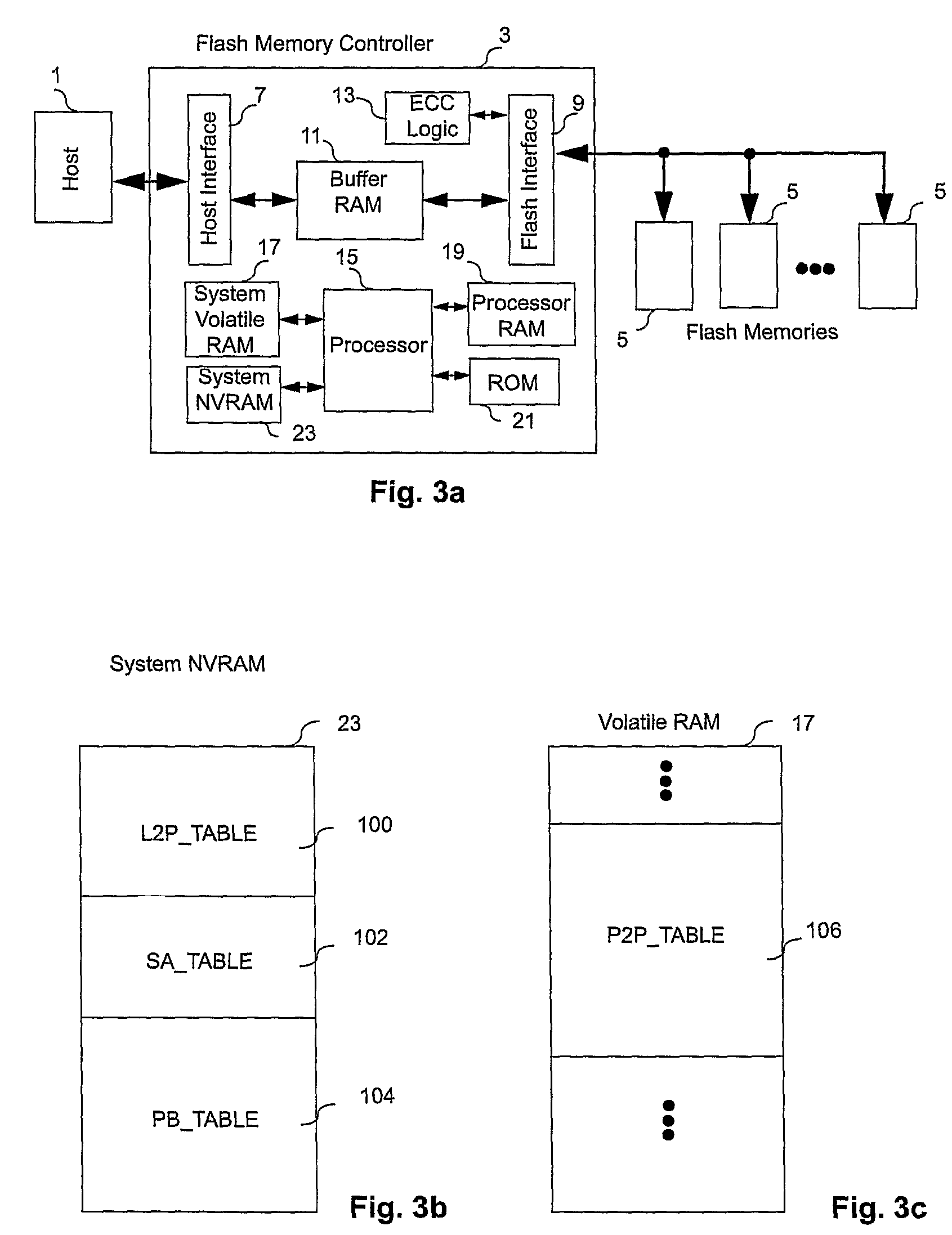
[0096]An embodiment of the present invention will now be described. The flash memory system typically has blocks shown in FIG. 3a, and the corresponding elements of the embodiment are given the same reference numbers as in FIG. 2. All elements shown in FIG. 3a are the same as FIG. 2, except that there is an additional system NVRAM memory device 23 incorporated into the flash controller. In FIG. 3a, the system NVRAM 23 is illustrated as a component within the flash controller 3, e.g. provided as part of a single integrated circuit which also integrates the other components of the flash controller 3. However, optionally, the NVRAM memory device 23 may be an external component connected to the flash controller 3 via a dedicated interface port.

[0097]One possible form of the embodiment is to assemble the flash controller 3 and the flash memories 5 into a single physical unit such as a memory card or a flash drive, and the interface to the host 1 (e.g. a personal computer) comprises a mat...


PUM


Abstract

A non-volatile memory system (3) is proposed consisting of a first non-volatile flash memory (5) having a plurality of blocks, each block having a plurality of pages, each block being erasable and each page being programmable, and a second non-volatile random access memory (23) having a plurality of randomly accessible bytes. The second non-volatile memory (23) stores data for mapping logical blocks to physical blocks and status information of logical blocks. Each logical block has an associated physical page pointer stored in the second non-volatile memory (23) that identifies the next free physical page of the mapped physical block to be written. The page pointer is incremented after every page write to the physical block, allowing all physical pages to be fully utilized for page writes. Furthermore, a method of writing and reading data is disclosed whereby the most recently written physical page associated with a logical address is identifiable by the memory system without programming flags into superseded pages, or recording time stamp values in any physical page or block of the first non-volatile memory (5). Furthermore, a method is provided for a logical block to be mapped to two physical blocks instead of one to provide additional space for page writes, resulting in reduction in page copy operations, thereby increasing the performance of the system.

Description

FIELD OF THE INVENTION[0001]This invention relates to a data storage system employing a solid state (i.e. semiconductor-type) non-volatile memory, such as a flash memory, and methods of operating such a memory. In particular, it relates to the construction, architecture and techniques of a flash memory controller for accessing such a non-volatile flash memory.BACKGROUND OF THE INVENTION[0002]Flash memory is a form of EEPROM (Electrically Erasable and Programmable Read Only Memory) that allows multiple memory locations to be erased or written in one programming operation. The memory is commonly used as a mass data storage subsystem for electronic devices, such as memory cards, USB (Universal Serial Bus) flash drives and solid-state drives as replacements of hard disk drives.[0003]A flash memory device consists of one or more arrays of transistor cells as its data storage units. Each of those cells is capable of keeping one or more bits of data even if the electric power supply is cut...

Claims


Application Information

Patent Timeline
Patent Type & Authority Patents(United States)
IPC IPC(8): G06F12/00
CPCG11C16/10G11C2029/1806
Inventor CHANG, CHEE KENG
Owner CHANG CHEE KENG
Why Eureka
Try Eureka