
Catalytic EGR oxidizer for IC engines and gas turbines

a technology of ic engines and catalysts, which is applied in the direction of machines/engines, bulk chemical production, separation processes, etc., can solve the problems of shortening the catalyst life, reducing the reliability and useful life of the reactor, and producing within a few milliseconds excess reaction heat, so as to improve the catalyst's durability and the effect of operating li

Inactive Publication Date: 2011-11-22
HWANG HERNG SHINN
View PDF32 Cites 98 Cited by
  • Summary
  • Abstract
  • Description
  • Claims
  • Application Information

AI Technical Summary

Benefits of technology

"The patent describes a catalytic oxidizer that can be installed in an engine or gas turbine to use the hot exhaust gas to initiate chemical reactions without needing an external heat source. The oxidizer uses a Pt group metal catalyst to produce hydrogen and carbon dioxide from the fuel, air, water, and recycled exhaust gas. The oxidizer can be used in conjunction with a fuel cell or battery to generate electricity. The technical effects of this invention include improved fuel utilization, reduced emissions, and improved power generation efficiency."

Problems solved by technology

However, despite all the necessary controls and the technology advances over the years, any internal combustion engine or gas turbine will still emit pollutants such as unburned hydrocarbons, CO, NOx, diesel particulates etc.
However, the reaction peak temperatures are frequently found to be exceeding the upper limits of the catalyst, and they would shorten the catalyst life and cause failures during the applications.
But for this primarily catalytic reactor system, water (or steam), CO2 or the recycle exhaust gas are not used in the feed gas to absorb the reaction heats as well as to perform steam reforming and water gas shift reactions.
Furthermore, since no precise control of O2 / C ratio is described, a sudden momentary increase in O2 / C ratio of the feed mixture can cause the run away oxidation reactions over the Pt group metal catalysts, and produce within a few milliseconds excess reaction heats.
These heats can permanently deactivate or even melt and destroy the catalysts, and thus reduce the reactor's reliability and its useful life.
However, despite the technology improvements in recent years, every fuel cell technology has limited short operating life, difficult for mass production, and still very expensive and unreliable.
For example, the Proton Exchange Membrane Fuel Cell (PEMFC) requires a constant and continuous supply of hydrogen to the stacks (i.e. electrodes) to generate electricity and thus, a reliable source of hydrogen becomes a limitation in this process.
Furthermore, fuel cell catalysts are sensitive to some residual hydrocarbons and / or impurities such as sulfur, calcium, magnesium, phosphors etc. and thus, the hydrogen fuel also needs to be purified, a yet further limitation of this process.
For example, a sudden increase / decrease in power requirement can cause flow disturbance to the reformer and thus create unstable operation in the fuel cell stacks.
However, this reaction zone must avoid the complete combustion reactions of hydrocarbons, because the complete combustion reactions at high O2 / C ratio>1.0 would produce CO2 and water instead of H2 and CO, and this CO2 cannot be used by most of the fuel cell stacks to generate electricity.
Since the rate of steam reforming reactions is much slower than that of the CPO reactions, the H2O / C ratio in the feed mixture has a limited effect on the reformer's overall hydrogen production.
However, though the synthetic gas was produced from natural gas by the catalytic partial oxidation reactions over a monolithic Rh catalyst, this pre-engine catalyst was not installed in the EGR line, and water was not used in the feed mixture.
Though some current models of passenger car and diesel truck are equipped with EGR line and some exhaust gas is re-circulated back to the engine for the purpose of reducing the engine's peak temperature and, thus, reducing the NOx emission, there are no commercial on-board catalytic reformers currently installed in the EGR line, and no fuel / water / air mixture injected into this reformer for the purpose of providing hydrogen to assist and to improve combustion's efficiency of an engine or a gas turbine

Method used


Image

  • Catalytic EGR oxidizer for IC engines and gas turbines
  • Catalytic EGR oxidizer for IC engines and gas turbines
  • Catalytic EGR oxidizer for IC engines and gas turbines

Examples


examples

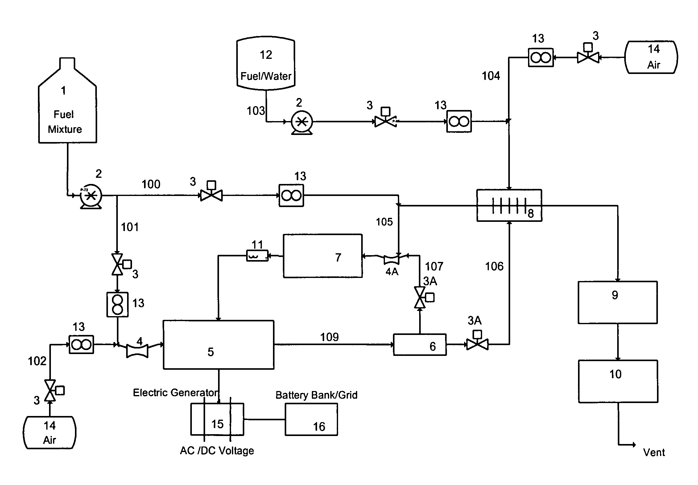
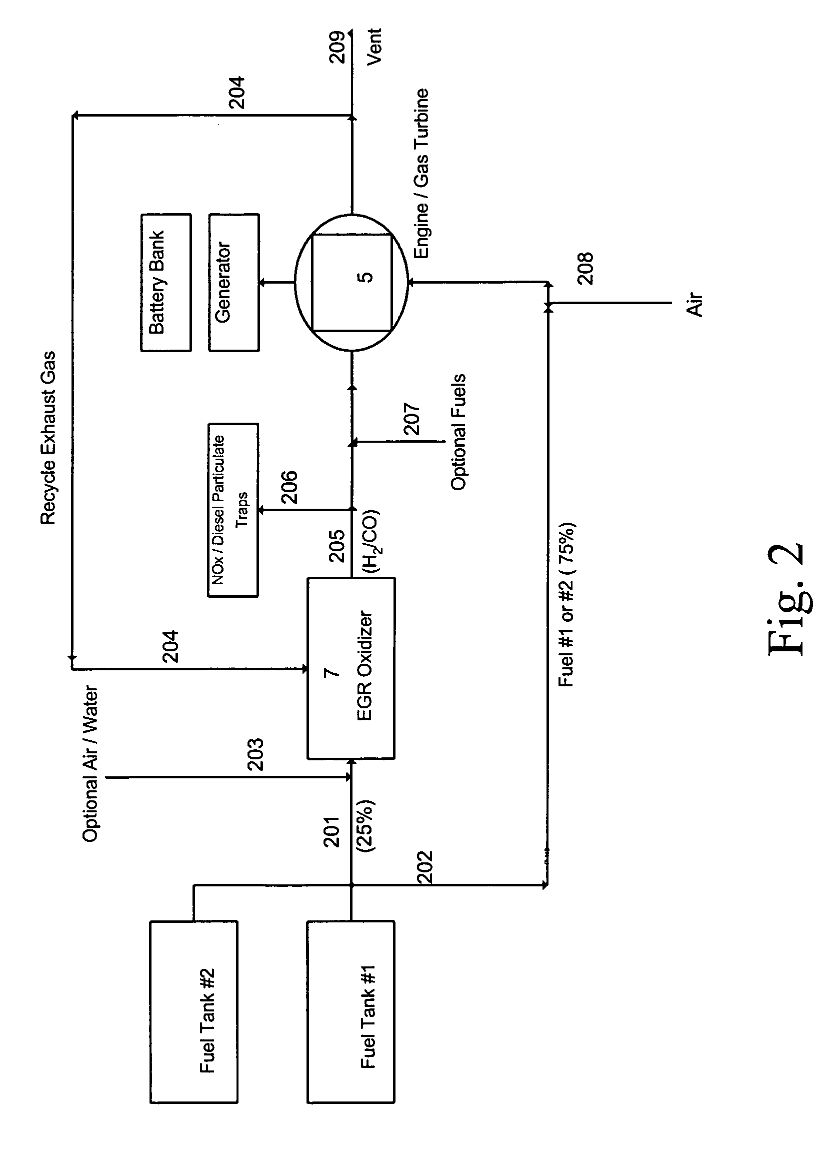
[0079]Depend on the control strategy on the air / fuel ratios, the exhaust gas composition coming from the automobile, small utility or diesel truck engines are different from each other. But normally the exhaust gas comprises approximately 14% steam, 10% CO2, 2, x, unburned hydrocarbons and balance N2. Therefore, to produce H2 and CO by the CPO reactions of the fuels and the recycled exhaust gas, it maybe necessary to inject additional amount of O2 into the EGR Oxidizer to increase the O2 / C ratio. For example, a simple “reed” valve, a carburetor, or a gas flow controller can be installed in the exhaust pipe for this purpose.

[0080]As described previously, catalytic partial oxidations of HC and bio-fuels over the Pt group metal catalysts has been studied over the years by several laboratories, and H2 and CO can successfully be produced at very high space velocities from fuels such as #2 diesel oil, gasoline, natural gas, LPG, jet fuel, ethanol, sugar-water, other bio-fuels etc. Therefo...


PUM

PropertyMeasurementUnit
temperatureaaaaaaaaaa

Abstract

By using catalytic partial oxidation or autothermal reforming process, a catalytic oxidizer installed in the engine's Exhaust Gas Recycle (EGR) line can be used to produce from fossil fuels or bio-fuels a reformate gas containing H2 and CO for an IC engine or a gas turbine. Thus, a system consisting of an EGR Oxidizer and an IC engine / gas turbine can be used by itself as a driving device, or can be combined with an electric generator and a battery bank to produce, store and transmit electricity to be used in stationary or mobile power generation, transportation and utility etc.The Oxidizer can also be used to provide reducing gases to regenerate the NOx or diesel particulate traps, so that the traps can continuously be used for reducing emissions from IC engine, diesel truck, gas turbine, power plant etc.

Description

CROSS REFERENCE INFORMATION[0001]This application claims benefit to and priority of U.S. Provisional Application No. 60 / 962,588 filed on Jul. 30, 2007, herein incorporated by reference in its entirety.BACKGROUND OF THE INVENTIONInternal Combustion Engines and Gas Turbines:[0002]In the 20th century, various types of internal combustion (IC) engines and gas turbines have successfully been developed and been widely used over the years in the stationary power generation, transportation and utility applications. For example, the 2-stroke and 4-stroke engines are used for motorcycle, chainsaw, lawn mower, weed eater, automobile, small power generator etc, the diesel engines are used for truck, bus, stationary power generator etc, and the gas turbines are used for airplanes, power generators etc. Currently, most of the IC engines and gas turbines utilize homogeneous flame combustion of various hydrocarbons (HC) to generate power, and it is known that the timing of ignition, the composition...

Claims


Application Information

Patent Timeline
Patent Type & Authority Patents(United States)
IPC IPC(8): F02B27/04C01B32/40
CPCB01D53/90B01D53/944C01B3/326C01B3/382C01B3/386C01B3/40C01B3/48F01N3/0253F01N3/0814F01N3/0842F02M25/0742B01D53/9409Y02P20/128B01D2251/202B01D2251/204B01D2255/1021B01D2258/012C01B2203/0244C01B2203/0261C01B2203/0283C01B2203/06C01B2203/085C01B2203/0861C01B2203/1005C01B2203/1011C01B2203/1023C01B2203/1029C01B2203/1041C01B2203/1047C01B2203/1052C01B2203/1058C01B2203/1064C01B2203/107C01B2203/1076C01B2203/1082C01B2203/1211C01B2203/1217C01B2203/1235C01B2203/1241C01B2203/1247C01B2203/84F01N2240/30Y02T10/121F02M26/36Y02P20/52Y02P20/10
Inventor HWANG, HERNG SHINN
Owner HWANG HERNG SHINN
Learn More