
Ionic liquid electrolyte

a liquid electrolyte and ionic liquid technology, applied in the direction of electrolytic capacitors, pv power plants, electrochemical generators, etc., can solve the problems of high viscosity, high viscosity, and loss of photovoltaic performance under prolonged thermal stress at 80° c, so as to improve the performance and stability of electrochemical and/or optoelectronic devices

Inactive Publication Date: 2012-02-14
ECOLE POLYTECHNIQUE FEDERALE DE LAUSANNE (EPFL)
View PDF20 Cites 11 Cited by
  • Summary
  • Abstract
  • Description
  • Claims
  • Application Information

AI Technical Summary

Benefits of technology

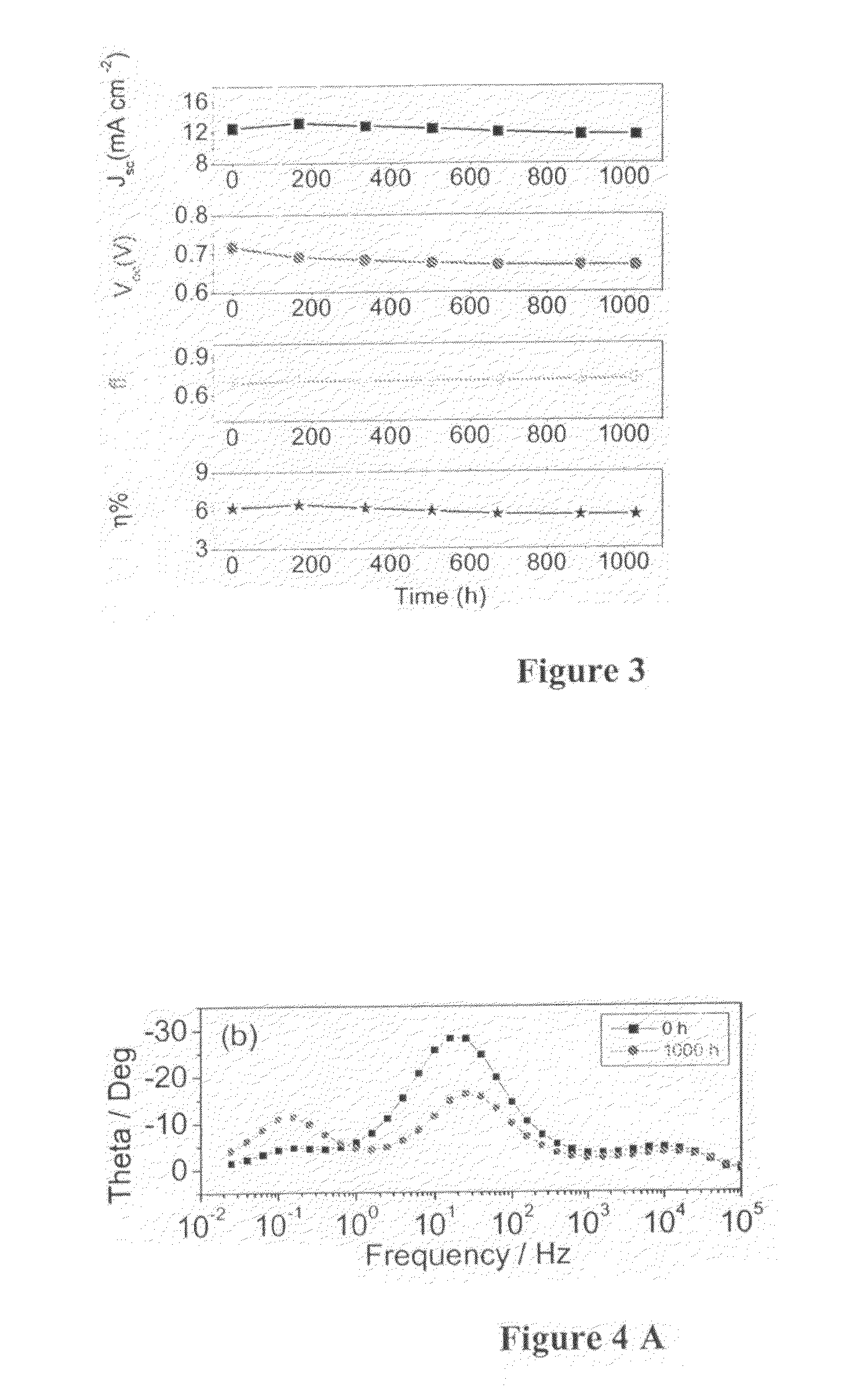
[0010]Surprisingly, the present inventors found that a ionic liquid based on a tetracyanoborate anion and an organic cation improve performance and stability of electrochemical and / or optoelectronic devices and in particular of sensitised solar cells. For the first time, in dye-sensitised solar cells using electrolytes comprising this ionic liquid, photovoltaic efficiency retained more than 90% of the initial value even after 1000 hours aging at 80° C. and light soaking at 60° C. These remarkable improvements solve problems linked to the above objectives and will foster industrial applications where one can use only ionic liquids electrolytes.

Problems solved by technology

Encapsulation and leakage of high vapor pressure organic solvents based electrolytes is a major challenge for the commercialization of many electrochemical and / or optoelectronic devices and in particular sensitized solar cells.
Imidazolium iodide ionic liquids, for example, are very viscous and the high concentration of iodide ions in these electrolytes creates a loss channel through reductive quenching of the excited sensitizer, hampering device performance.
Various binary ionic liquid electrolytes have recently been applied to dye-sensitised solar cells reaching over 7.0% photovoltaic conversion efficiency with a good stability under accelerated light soaking tests at 60° C. However, the drawback of the anions thiocyanate, selenocyanate, dicyanamide and tricyanomethanide that have been used along with iodide to attain such an impressive performance is their thermal instability resulting in photovoltaic performance loss under prolonged thermal stress at 80° C.
Disadvantages of iodide ions are, for example, the high viscosity and low efficiency of electrolytes containing them.

Method used


Image

  • Ionic liquid electrolyte
  • Ionic liquid electrolyte
  • Ionic liquid electrolyte

Examples


example 1

Ionic Liquids, Electrolytes and Diffusion Coefficient

[0091]A ionic liquid EMIB(CN)4 (1-ethyl-3-methylimidazolium tetracyanoborate) was obtained from Merck, Germany. Its synthesis is further disclosed in WO 2004 / 072089, page 18, Example 9. The viscosity of EMIB(CN)4 is 19.8 cP at 20° C.

[0092]A binary ionic liquid, “electrolyte A” was composed of 0.2 M I2, 0.5 M NMBI (N-Methylbenzimidazole) and 0.1 M guanidinium thiocyanate (GuNCS) in a mixture of PMII (1-methyl-3-propylimidazolium) iodide and EMIB(CN)4 (volume ratio: 13:7). PMII was prepared according to Bonhôte, P. et al Inorg. Chem. 1996, 35, 1168-1178.

[0093]For comparison, another binary ionic liquid electrolyte B was prepared using 0.2 M I2, 0.5 NMBI and 0.1 M GuNCS in PMII.

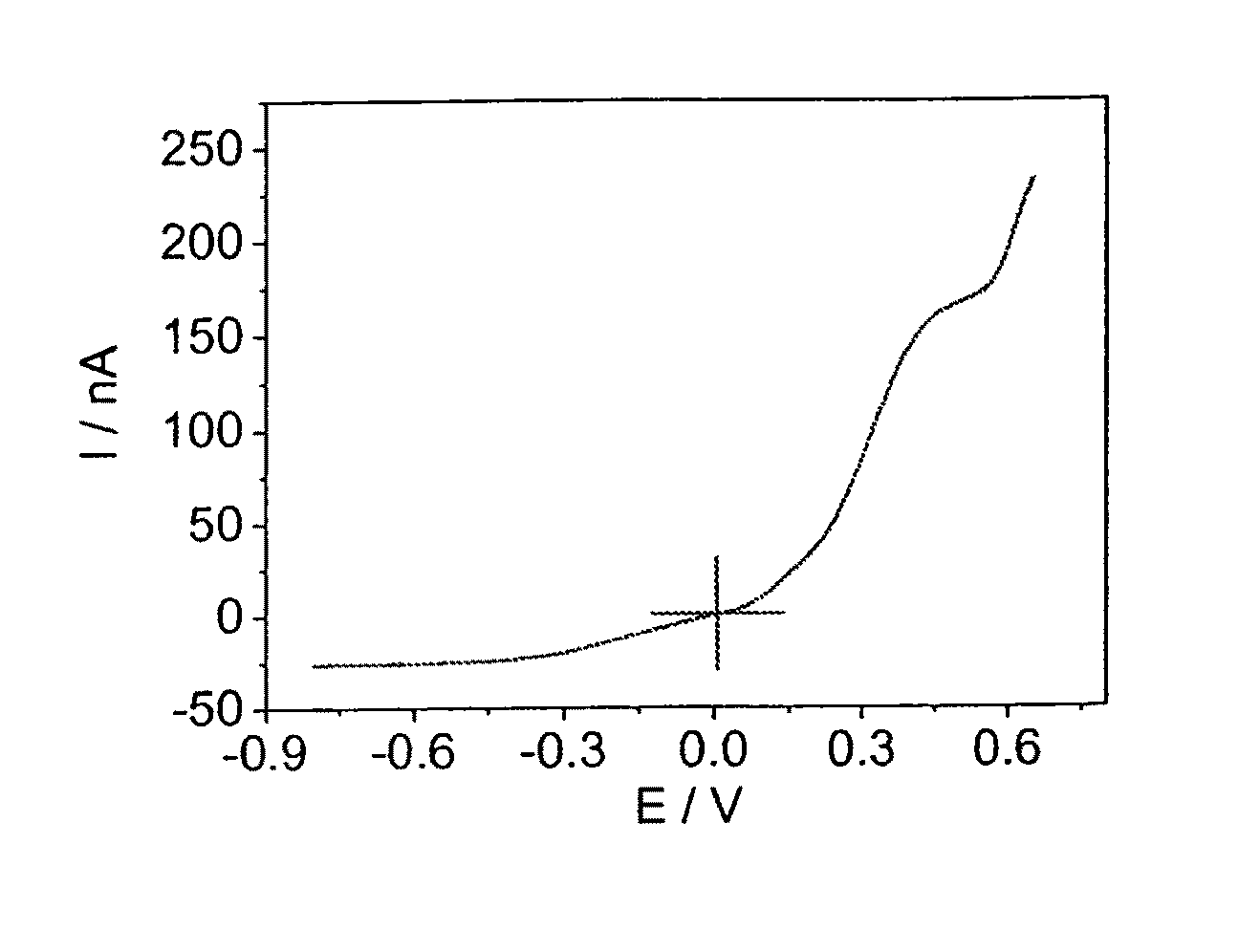
[0094]The diffusion coefficients of iodide and triiodide were measured as described in Bard, A. J.; Faulkner, L. R. Electrochemical Methods: Fundamentals and Applications, 2nd ed: Weinheim, 2001. The apparent diffusion coefficient of iodide and triiodide calcu...

example 2

Fabrication of Dye-Sensitized Solar Cells

[0096]A double-layer, mesoporous TiO2 electrode was prepared as disclosed in Wang, P., Zakeeruddin, S. M., Comte, P., Charvet, R., Humphry-Baker, R. Grätzel M., Enhance the Performance of Dye-Sensitized Solar Cells B Co-Grafting Amphiphilic Sensitizer and hexadecylmalonic Acid on TiO2 Nanocrystals M. J. Phys. Chem. B 2003, 107, 14336, in particular page 14337, in order to obtain a photoanode consisting of a double layer structure, with a transparent layer (20 nm particle) and scattering layer (400 nm particle) of 6.8 μm and 4 μm thickness, respectively.

[0097]The electrode was sintered and coated with Z-907 Na dye by dipping it into the dye solution as disclosed in the same reference above (300 μM Z-907Na is disclosed in Wang Peng, Wenger B, Humphry-Baker R, Teuscher J, Kantlehr W, Mezger J, Stoyanov E:V, Zakeeruddin Shaik M and Graetzel M; Charge separation and efficient light energy conversion in sensized mesoscopic solar cells based onbinar...

example 3

Characteristics of the Dye-Sensitized Solar Cells

[0099]The measurement of current-voltage curves and incident photon-to-current conversion efficiency (IPCE) of the cells were obtained by using a Keithley model 2400 digital source meter (Keithley, USA) under an applied external potential bias as reported in the reference cited above of Wang et al J. Phys. Chem. B 2003, 107, 14336.

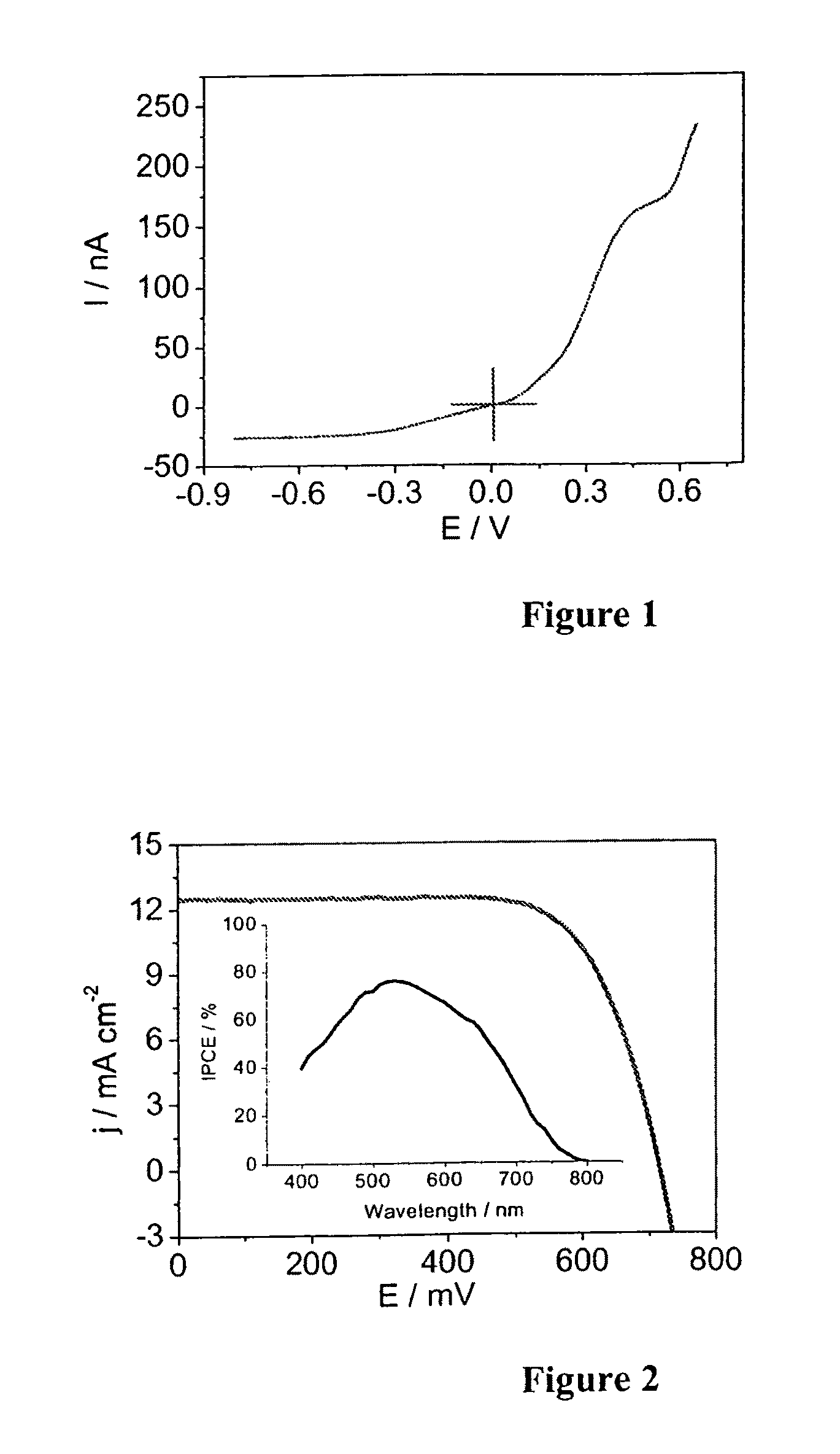
[0100]The photocurrent-voltage curves of devices A based on Z-907Na sensitizer and electrolyte A measured under AM-1.5 full sunlight illumination is shown in FIG. 2.

[0101]The photocurrent action spectrum of devices A (inset of FIG. 2) shows that the incident photon to current conversion efficiency (IPCE) is close to 80% at 530 nm. Detailed photovoltaic conversion efficiencies of devices A and B at various light intensities are shown in Table 1 below.

[0102]

TABLE 1Photovoltaic parameters of devices A and B at different light intensitiesη (%) at different light intensityElectrolyte1.0 sun0.5 sun0.3 sunA6.47.17....


PUM

PropertyMeasurementUnit
vol. %aaaaaaaaaa
melting pointaaaaaaaaaa
temperatureaaaaaaaaaa

Abstract

The present invention relates to electrolytes comprising tetracyanoborate and an organic cation as components of electrolytes in electrochemical and / or optoelectronic devices, in particular solar cells. This ionic liquid has low viscosity and can be used as electrolyte in the absence of a solvent. Importantly, the ionic liquid remains stable in solar cells even after prolonged thermal stress at 80° C. for 1000 hours. Photovoltaic conversion efficiency remained stable and keeping more than 90% of the initial value.

Description

[0001]This application claims the benefits under 35 U.S.C. 119(a)-(d) or (b), or 365(b) of International Application No. PCT / IB2007 / 050472 filed 13 Feb. 2007, and European Patent Application No. 06101577.2 filed 13 Feb. 2006.[0002]The present invention relates to electrochemical and / or optoelectronic devices, to new electrolytes, to the use of a ionic liquid in such a device and to a method for preparing a photoelectric cell.BACKGROUND ART AND PROBLEM TO BE SOLVED[0003]Electrolytes form a crucial part of electrochemical and / or optoelectronic devices and performance of the device largely depends on the physical and chemical properties of the various components of these electrolytes.[0004]Amongst solar cells, those sensitised with a dye or quantum dots for example, have been paid intensive attentions in the last 15 years as an alternative to silicon technology and progresses have been made in the development of efficient dyes, electrolytes and TiO2 films to enhance the device performa...

Claims


Application Information

Patent Timeline
Patent Type & Authority Patents(United States)
IPC IPC(8): H01B3/20H01M10/052H01M10/0561H01M10/36
CPCH01G9/2013H01G9/2031H01G9/2059H01M10/052H01M10/0561H01M2300/0045Y02E10/542Y02E60/10H01M10/0566H01L31/04H10N10/856
Inventor KUANG, DAIBINWANG, PENGZAKEERUDDIN, SHAIK MOHAMMADGRAETZEL, MICHAËL
Owner ECOLE POLYTECHNIQUE FEDERALE DE LAUSANNE (EPFL)
Learn More