Hybrid Brayton cycle with solid fuel firing

a brayton cycle and solid fuel technology, applied in the field of power generation, can solve the problems of inability to demonstrate the power and efficiency levels of the system to justify itself economically, the cost of higher complexity and cost, and the practical equipment is limited in the pressure ratio that can be efficiently operated, so as to achieve the effect of reducing the total cost of production, increasing the mass of flow through the turbine, and speeding up the response tim

Inactive Publication Date: 2012-05-15
SMITH DOUGLAS W P
View PDF7 Cites 13 Cited by
  • Summary
  • Abstract
  • Description
  • Claims
  • Application Information

AI Technical Summary

Benefits of technology

[0033]This patent application teaches a hybrid Brayton cycle system that overcomes the limitations of previously known externally-heated Brayton systems including the maximum power limitation and the overall efficiency losses inherent in such systems and further allows for a partial power control approach that overcomes the problem of slow system response times. The invention of the present patent application comprises adding water to the working fluid prior to entering recuperator (8) and prior to entering heater (9), with the result of evaporative cooling of the working fluid and increase in the mass of flow through turbine (2), more energy transferred in the heat exchangers and more overall energy converted to work output (4). The invention also comprises using only a portion of the flow of turbine output air (22) for combustion, which allows a new control approach such that faster response times and greater efficiency can be achieved.
[0035]Hybrid Brayton cycles of the present invention, shown in FIG. 4 and FIG. 5 mitigate both limiting features of the externally-heated Brayton cycle. Recuperator spray (34) cools pressurized air (12) due to evaporative cooling. A lower temperature and higher mass flow of cool pressurized fluid (13) (air plus water vapor) introduced into recuperator (8) allows more energy to transfer into recuperated air (14). Moisture spray (36) cools recuperated air (14) due to evaporative cooling. A lower temperature and higher mass flow of cool recuperated fluid (15) (air plus water vapor) introduced into heater (9) allows more energy to transfer into heated air (16). The added mass of recuperator spray (34) and heater spray (36) mitigates the mass loss of fuel input (32) of the internally-heated Brayton cycle of said example in FIG. 1.

Problems solved by technology

The few such systems that have been produced have failed to show power and efficiency levels to justify themselves economically.
Others have used testing to discover the limitations and may or may not understand the technical reasons for them.
Practical equipment is limited in the pressure ratio that can be efficiently used across a single stage of expansion and similarly across a single stage of compression.
Multiple stages of expansion are often used to maximize efficiency of producing useful work but at the expense of higher complexity and cost.
Higher temperatures entering the turbine increases the work produced but requires greater fuel flow rates to obtain.
This unused energy is seldom recovered within in larger systems because the size of the heat exchanger, external piping and pressure losses would not justify the efficiency benefit realized.
Disadvantages to such externally-heated Brayton systems, described in greater detail below, include lower mass flow through the turbine, additional pressure drops, reduced temperature due to heat exchanger energy transfer and further reduction in temperature to accommodate metal temperature limitations.
Reduced mass flow of heated air (16) passing through turbine (2) results in a loss of power when converting from an internally-heated to an externally-heated Brayton cycle.
Pressure losses detract from the work efficiency of any Brayton cycle system.
Thus the same energy input to the system results in reduced work output by the turbine which means the efficiency of an externally-heated Brayton cycle will be less than the efficiency of an internally-heated Brayton cycle.
Metal temperature limitations introduce an additional loss of efficiency in a practical externally-heated Brayton cycle system.
Available metals for this service will typically restrict the allowable temperature of the heat source entering the heater.
Attempts have been made to use non-metal exchangers and piping to increase the operating temperatures but it is a difficult and expensive proposition.
An externally-heated Brayton cycle that uses an independent heat source such as a waste heat stream has competing parameters that limit the benefits of recuperation.
Thermodynamic analysis shows that this loss of energy entering the cycle will decrease the overall system efficiency thus working in opposition to the cycle efficiency increase due to recuperator (8).
The lower temperature of heated air (16) entering turbine (2) results in less work output (4) and thus lower system efficiency.
A further temperature limitation for hot flue gas (16) is required to meet metal temperature restrictions of heater (9) which therefore restricts heated air temperature (16) further, reduces work output (4) and lowers system efficiency further.
There are practical issues that arise in the operation of the FIG. 3 arrangement.
The first issue is that the temperature of turbine exhaust (22) is very high for introduction into standard combustion equipment.
The second issue is the effects of operating at partial power levels.
It can be seen that greatly limited maximum power and low electrical conversion efficiency are inherent shortcomings of the current state of the art of externally-heated Brayton systems.

Method used


Image

  • Hybrid Brayton cycle with solid fuel firing
  • Hybrid Brayton cycle with solid fuel firing
  • Hybrid Brayton cycle with solid fuel firing

Examples


Embodiment Construction

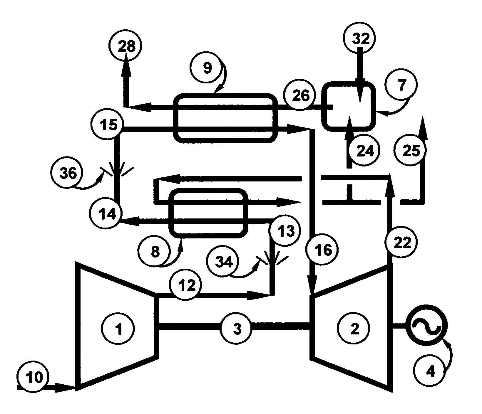
[0053]Thermodynamic analysis shows that operating equipment from said example of FIG. 1 in the configuration of FIG. 4, “Recuperated Hybrid Brayton Cycle With Independent Heat Source”, with said common input parameters and operating at a slightly lower rotational speed of shaft (3) for best efficiency results in said comparison maximum power production of 100% (equal to said example of FIG. 1) and overall efficiency about 16.3%. These results assumed a temperature for heater spray (36) and recuperator spray (34) of 60° F. (15.6° C.) and volume flow of each sufficient to generate 90% relative humidity downstream. Cooled exhaust (24) is 378° F. (192° C.), is clean with full oxygen content and is available as a source of heat or hot combustion air.

[0054]Thermodynamic analysis shows that operating equipment from said example of FIG. 1 in the configuration of FIG. 5, “Recuperated Hybrid Brayton Cycle With Dependent Heat Source”, with said common input parameters and operating at a slight...


PUM


Abstract

This invention provides a method of converting heat energy to a more usable form using an externally-heated Brayton cycle. Atmospheric air is used with water injection in a thermodynamic cycle that includes compression (1), evaporative cooling (34), recuperative heating (8), evaporative cooling (36), external heating (9) and expansion through a turbine (2). Power capacity and overall efficiency are maximized by decreasing the temperature of working fluid entering recuperator (8) and heater (9) while increasing the mass flow through turbine (2). Overall efficiency during turndown is maximized using a portion of low-pressure working fluid from the turbine in a three-chamber combustor wherein volume flow into the first chamber containing solid fuel determines the system energy, volume flow into the second chamber combines with partially combusted gases from the first chamber to achieve the optimum combustion temperature and volume flow into the third chamber blends with combustion gases from the second chamber to limit the hot gas to the maximum temperature allowed by the system equipment.

Description

TECHNICAL FIELD OF THE INVENTION[0001]This invention relates to the field of power generation by applying the thermodynamic power cycle known as the Brayton cycle, as used in gas turbines and jet engines, in an externally-heated configuration.BACKGROUND OF THE INVENTION[0002]Over the years a number of individuals and companies have proposed applying the Brayton-cycle in an externally-heated arrangement. (For example, Wolf, J., F. Barone and J. Yan, Performance Analysis of Evaporative Biomass Air Turbine Cycle With Gasification for Topping Combustion, Journal of Engineering for Gas Turbines and Power, Vol. 124 p. 757, 2002; Jonsson, Maria, Advanced Power Cycles with Mixtures as the Working Fluid, Doctoral Thesis, Department of Chemical Engineering and Technology, Energy Processes, Royal Institute of Technology, Stockholm, Sweden, 2003; UK Department of Trade and Industry reports URN Number 02 / 1346, Biomass Combustion Gas Turbine CHP, 2002. and URN Number: 05 / 698, Biomass Fuelled Indi...

Claims


Application Information

Patent Timeline
Patent Type & Authority Patents(United States)
IPC IPC(8): F02C7/00F02C1/04F01K25/02F02G3/00F02G1/00
CPCF01K7/16F01K17/02F01K21/04Y02E20/14
Inventor SMITH, DOUGLAS W. P.
Owner SMITH DOUGLAS W P
Why Eureka
Try Eureka