Catalyst-supporting particle, composite electrolyte, catalyst electrode for fuel cell, and fuel cell using the same, and methods for fabricating these

a fuel cell and catalyst electrode technology, applied in the field of catalyst electrodes for fuel cells and fuel cells, can solve the problems of limiting the output power of the fuel cell, reducing the efficiency of the cell, and loss of fuel not reacted in the fuel electrode, so as to achieve the effect of suppressing the output power reduction, reducing the output power, and increasing the output power

Inactive Publication Date: 2012-08-07
NEC CORP
View PDF23 Cites 3 Cited by
  • Summary
  • Abstract
  • Description
  • Claims
  • Application Information

AI Technical Summary

Benefits of technology

[0018]In the catalyst-supporting particle for the fuel cell of the present invention, the adhesive layer disposed between the carbon particle and the catalyst metal has the affinity to both of the carbon particle and the catalyst metal. In this configuration, the contact area of the catalyst metal with the carbon particle surface having the adhesive layer on the surface can be increased.
[0046]In this manner, the present invention provides the catalyst-supporting particle for the fuel cell, the composite electrolyte and the catalyst electrode, by disposing the adhesive layer between the carbon particle and the catalyst substance, in which the contact resistance between the catalyst substance and the carbon particle supporting the same is smaller, and the aggregation of the catalyst substance is suppressed. Further, the fuel cell having the higher output power and the excellent durability, and the method of fabricating the same are realized.

Problems solved by technology

An inferior adhesion at the interface increases the electric resistance due to the decrease of the conductivity of the hydrogen ions to cause a reduction of the cell efficiency.
The main electric losses include those due to resistance over voltage, activation over voltage and concentration over voltage, and the loss of fuel not reacted in the fuel electrode.
That is, the diffusion resistance of electrons generated on the fuel electrode from the catalyst substance to the carbon particle is increased to limit the output power of the fuel cell.

Method used


Image

  • Catalyst-supporting particle, composite electrolyte, catalyst electrode for fuel cell, and fuel cell using the same, and methods for fabricating these
  • Catalyst-supporting particle, composite electrolyte, catalyst electrode for fuel cell, and fuel cell using the same, and methods for fabricating these
  • Catalyst-supporting particle, composite electrolyte, catalyst electrode for fuel cell, and fuel cell using the same, and methods for fabricating these

Examples


example 1

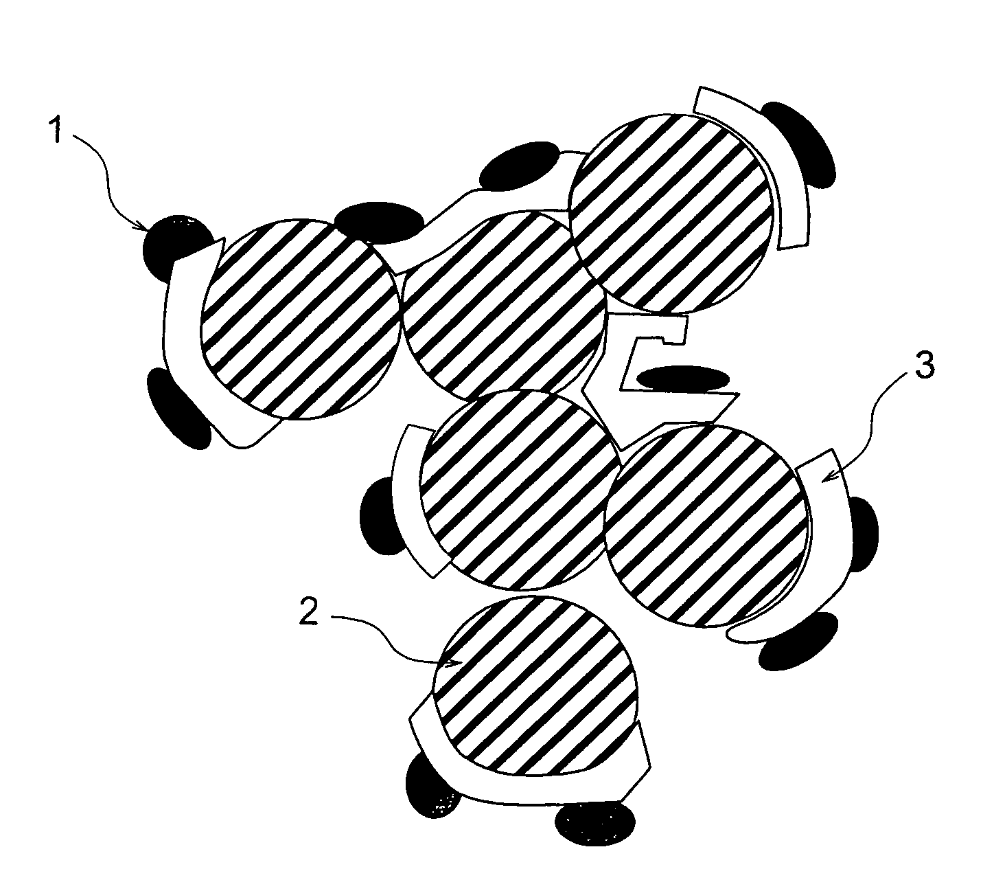
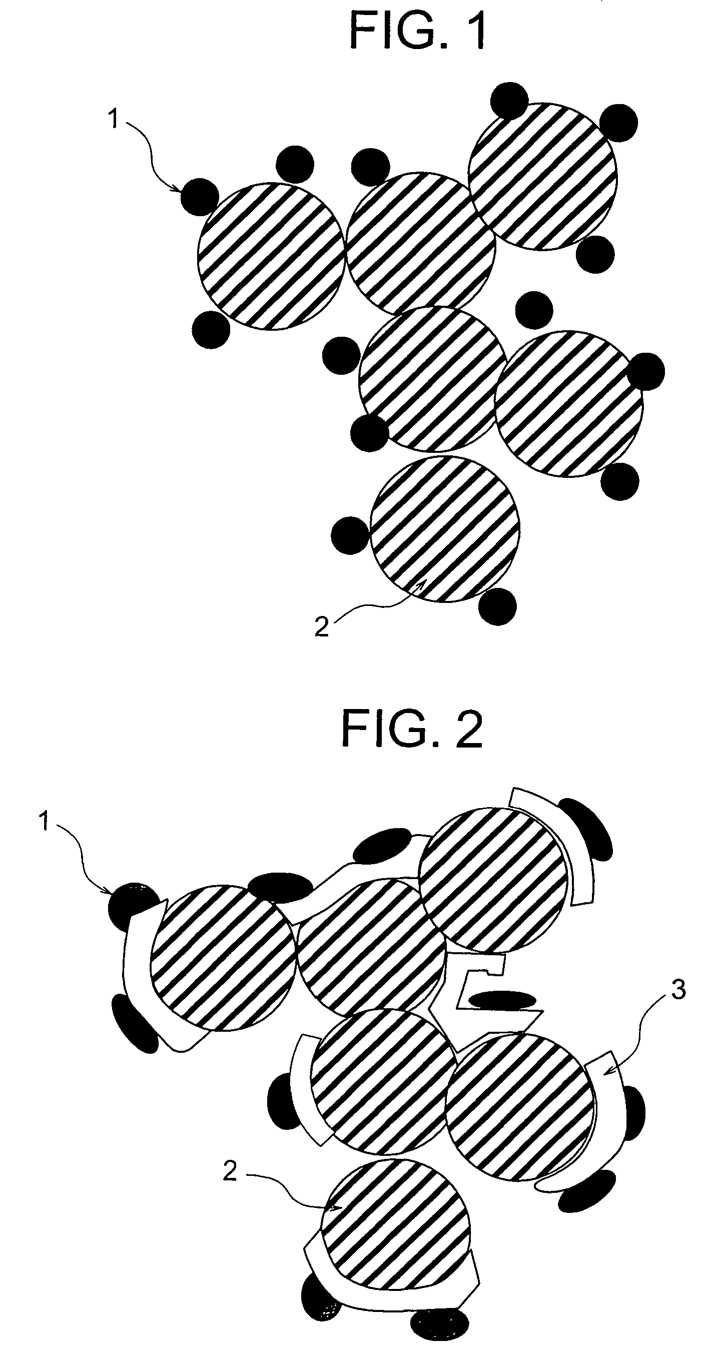
[0091]The preparation and the evaluation of catalyst-supporting particle having a carbon particle, a catalyst substance and an adhesive layer sandwiched between the carbon particle and the catalyst substance were conducted in accordance with the following methods.

[0092]Ketjen black (available from Lion Corporation) was used as the carbon particle for supporting the catalyst. An aqueous solution was prepared by dissolving 1 g of titanium tetrachloride into 1 liter of pure water. After the aqueous solution was cooled with ice water and 10 g of the ketjen black was added and agitated, the titanium was adsorbed on the ketjen black surface. After the filtrations of the carbon particles supporting the titanium and the washings were repeated several times, a metal titanium layer was formed on the carbon particle surface by placing the particles in an argon atmosphere and heating to 500° C. The observation of the carbon particles at this stage with a transmission electron microscope (TEM) c...

example 2

[0100]The preparation and the evaluation of catalyst-supporting particle having a carbon particle, a catalyst substance and an adhesive layer sandwiched between the carbon particle and the catalyst substance were conducted in accordance with the following methods.

[0101]Acetylene black (available from Denki Kagaku Kogyo K.K.) was used as the carbon particle for supporting the catalyst. An aqueous solution was prepared by dissolving 1 g of zirconium tetrachloride into 1 liter of pure water. After the aqueous solution was cooled with ice water and 10 g of the acetylene black was added and agitated, the zirconium was adsorbed on the acetylene black surface. After the filtrations of the carbon particles supporting the zirconium and the washings were repeated several times, a metal zirconium layer was formed on the carbon particle surface by placing the particles in a helium atmosphere and heating to 500° C. The observation of the carbon particles at this stage with the TEM confirmed the ...

example 3

[0108]Catalyst electrodes and fuel cells were fabricated by using the two kinds of the catalyst-supporting carbon particles prepared in Example 1 and the catalyst-supporting carbon particle prepared in Example 2.

[0109]A colloidal dispersion liquid of a polymer electrolyte was prepared by mixing a solid polymer electrolyte which was an alcohol solution containing 5% Nafion available from Aldrich Chemical Co. with n-butyl acetate such that an amount of the solid polymer electrolyte was adjusted to be 0.1 to 0.4 mg / cm2, followed by agitation. Then, each 500 g of the above three kinds of the carbon particles supporting the platinum catalysts was added to 80 ml of the colloidal dispersion liquids of the polymer electrolytes prepared above to adsorb the colloids on the carbon particle surfaces. These dispersion liquids were made to be pastes by using a supersonic wave dispersion apparatus.

[0110]After the obtained pastes were applied on carbon papers (available from Toray Industries, Inc.)...


PUM

PropertyMeasurementUnit
particle diameteraaaaaaaaaa
radiusaaaaaaaaaa
atomic radiusaaaaaaaaaa

Abstract

An adhesive layer 3 is disposed between a carbon particle 2 and a catalyst substance 1 of a catalyst-supporting particle for a fuel cell containing the carbon particle 2 and the catalyst substance 1. Thereby, the catalyst-supporting particle for fuel cell can be obtained in which a contact resistance between the catalyst substance and the carbon particle supporting the same is lower, and the aggregation of the catalyst substance is suppressed. A catalyst electrode for a fuel cell and the fuel cell using the above particle have a higher output power and an excellent durability.

Description

TECHNICAL FIELD[0001]The present invention relates to a catalyst-supporting particle for a fuel cell, and a composite electrolyte, a catalyst electrode for a fuel cell and a fuel cell using the same, and methods for fabricating these.BACKGROUND ART[0002]A polymer electrolyte fuel cell is a power-generating apparatus by causing an electrochemical reaction while supplying hydrogen to a fuel electrode and oxygen to an oxidant electrode. The fuel electrode and the oxidant electrode are bonded to the respective surfaces of a solid polymer electrolyte membrane containing perfluorosulfonic acid acting as an electrolyte[0003]The following reactions take place in the respective electrodes.Fuel Electrode: H2→2H++2e−Oxidant Electrode: ½O2+2H++2e−→H2O[0004]A higher output power of 1 A / cm2 or more can be obtained at ambient temperatures and atmospheric pressure in accordance with these reactions in the polymer electrolyte fuel cell.[0005]In the fuel electrode and the oxidant electrode, there are...

Claims


Application Information

Patent Timeline
Patent Type & Authority Patents(United States)
IPC IPC(8): B01J21/18B32B21/02B32B23/02B32B9/00B32B5/16B32B27/02B01J23/40B01J23/00B01J23/74B32B15/02B32B17/02B32B19/00B01J23/42B01J23/89B01J37/02B01J37/08H01M4/86H01M4/88H01M4/92H01M8/02H01M8/10
CPCB01J23/42B01J23/89B01J37/024B01J37/08H01M4/8828H01M4/926H01M8/1004H01M4/8605B01J21/18Y10T428/2991Y02E60/521Y02P70/50Y02E60/50
Inventor YOSHITAKE, TSUTOMUNAKAMURA, SHINKUROSHIMA, SADANORIKIMURA, HIDEKAZUIMAI, HIDETOSHIMAKAWA, YUICHIMANAKO, TAKASHIKUBO, YOSHIMI
Owner NEC CORP
Why Eureka
Try Eureka