Method for manufacturing plugged honeycomb structure

a technology of honeycomb and manufacturing method, which is applied in the direction of catalyst carriers, ceramicware, physical/chemical process catalysts, etc., can solve the problems of long time spent for forming membranes of desired amount, high yield of raw materials, and low waste of raw materials

Active Publication Date: 2012-10-02
NGK INSULATORS LTD
View PDF10 Cites 67 Cited by
  • Summary
  • Abstract
  • Description
  • Claims
  • Application Information

AI Technical Summary

Benefits of technology

[0016]Since the manufacturing method of a plugged honeycomb structure of the present invention has a process where ceramic particles are mixed with a gas on the one end face side of the plugged honeycomb structure and a process where the gas containing the ceramic particles is sucked from the other end face side of the plugged honeycomb structure to send the ceramic particles mixed in the gas into the cells of the plugged honeycomb structure to allow the ceramic particles to adhere to the surfaces of the cells of the plugged honeycomb structure, ceramic particles are successfully supplied to the cells, and ceramic particles can be inhibited from adhering to and depositing on the inlet end or the terminal end of the cells (The ends means the portions in the vicinity of the end faces of the plugged honeycomb structure, and, between these ends, the inlet end is the end on the ceramic particle supply side, and the terminal end is the cell inside of the plugging portion.) In addition, in comparison with the case of sending the ceramic particles with a gas under pressure, scattering of the particles is suppressed to reduce the waste, and the manufacturing environment is improved.
[0024]When the density of the ceramic particles is below 1 g / m3, ceramic particles easily passes through the pores of the substrate without forming a bridge, and thereby the yield may fall. In addition, the time spent for the membrane formation is increased to raise the production costs of the plugged honeycomb structure with surface trapping layers. On the other hand, when the density of the ceramic particle is above 1600 g / m3, ceramic particles aggregate together to cause adhesion and deposition of the ceramic particles at the cell inlets (end face of the plugged honeycomb structure), and biased deposition of the ceramic particles is caused in the cells, which makes the formation of homogeneous membranes difficult.

Problems solved by technology

However, in such a plugged honeycomb structure, since PM enters the inside of the porous article (substrate) to clog the pores, pressure loss is prone to increase rapidly.
However, in the manufacturing methods disclosed in JP-A-10-249124 and JP-A-2006-685, the input raw material (ceramic particles) does not form trapping layers efficiently to waste the raw material, and long time is spent for forming membranes of a desired amount.
Further, upon membrane formation, when the amount of ceramic particles contained in the gas for conveying the ceramic particles is large, ceramic particles are prone to aggregate, and the ceramic particles do not deposit uniformly to form membranes in a biased state.

Method used


Image

  • Method for manufacturing plugged honeycomb structure
  • Method for manufacturing plugged honeycomb structure
  • Method for manufacturing plugged honeycomb structure

Examples


examples 1 to 9

[0105]There were mixed and kneaded 80 parts of silicon carbide, 20 parts of metal silicon, 13 parts of coke having an average particle diameter of 10 μm as a pore former, 35 parts of water as a dispersion medium, 6 parts of hydroxypropylmethyl cellulose as an organic binder, and 0.5 part by mass of ethylene glycol as a dispersant to prepare kneaded clay. Next, the kneaded clay was subjected to extrusion forming using a die having a quadrangular cell shape and a predetermined slit width to obtain a honeycomb-shaped substrate having an entire shape of prismatic column (cylinder). After the honeycomb-shaped substrate was dried with a microwave drier and further completely dried with a hot air drier, a mask was alternately applied to cell opening portions on an end face of the honeycomb-shaped substrate, and the end portion having the mask was immersed in plugging slurry containing the aforementioned silicon carbide to form plugging portions disposed alternately in a checkerwise pattern...

examples 10 to 12

[0128]There were mixed and kneaded 100 parts of cordierite forming raw material obtained by mixing alumina, aluminum hydroxide, kaolin, talc, and silica, 13 parts of coke having an average particle diameter of 10 μm as a pore former, 35 parts of water as a dispersion medium, 6 parts of hydroxypropylmethyl cellulose as an organic binder, and 0.5 part of ethylene glycol as a dispersant to prepare kneaded clay. Next, the kneaded clay was subjected to extrusion forming using a die having a predetermined slit width for alternately forming octagonal cells and quadrangular cells to obtain a honeycomb-shaped substrate having an entire shape of circular column (cylinder) having octagonal cells and quadrangular cells. After the honeycomb-shaped substrate was dried with a microwave drier and further completely dried with a hot air drier, a mask was alternately applied to cell opening portions on an end face of the honeycomb-shaped substrate, and the end portion having the mask was immersed in ...

example 13

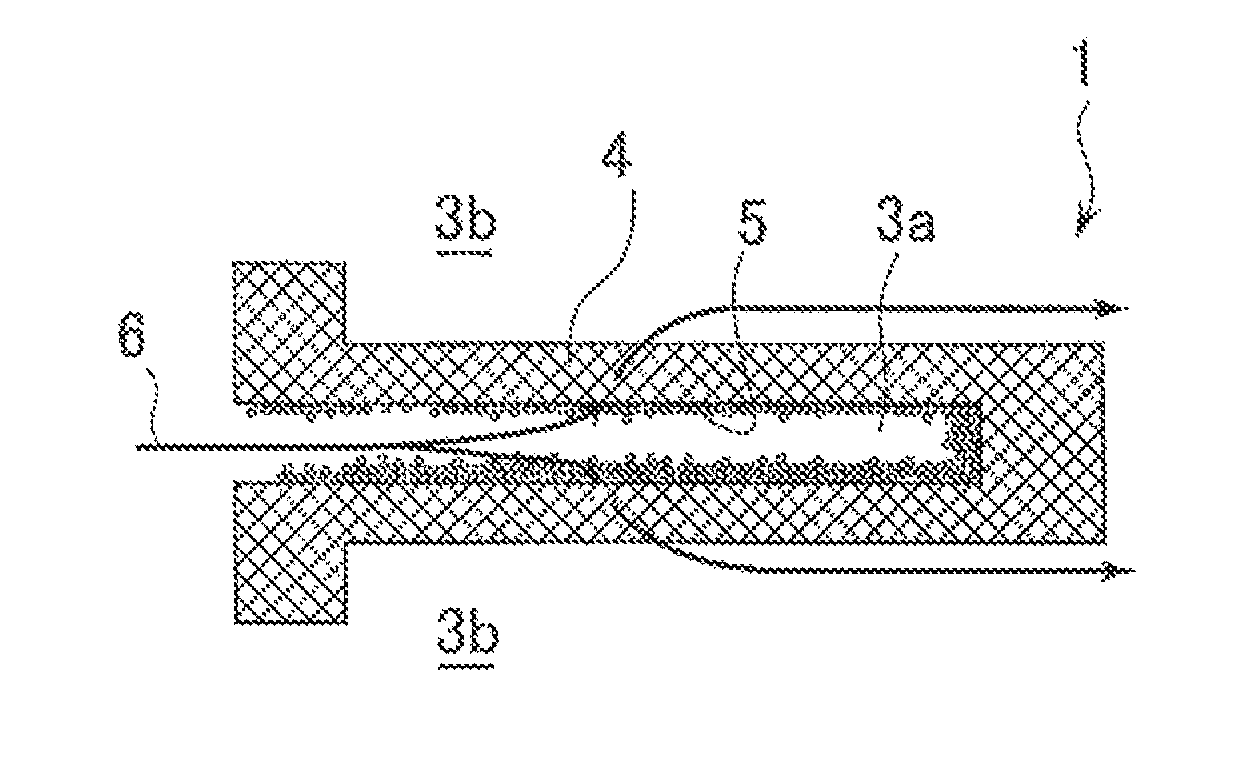
[0130]Silicon carbide was used as the framework particles to manufacture a quadrangular columnar plugged honeycomb structure, and membranes were formed on the plugged honeycomb structure on the basis of the second membrane forming method described above. Then, the plugged honeycomb structure (having trapping layers by membrane formation), before bonding, was subjected to a thermal treatment without performing end face removal, and the structure was evaluated as a plugged honeycomb structure with surface trapping layers. The other conditions were the same as in Example 3. The results are shown in Table 1.

[0131](Discussion)

[0132]From Examples 1 to 5 and 10 to 12, it is understood that, when the aerosol density is below 1.0 g / m3, the raw material yield falls to a large extent and, when the aerosol density is above 1600 g / m3, the pressure loss reduction rate with PM becomes small.

[0133]In addition, from Examples 1 to 4 and 6 to 11, it is understood that, in the case that the aerosol den...


PUM

PropertyMeasurementUnit
pore sizeaaaaaaaaaa
porosityaaaaaaaaaa
pore sizeaaaaaaaaaa

Abstract

A method for manufacturing a plugged honeycomb structure including a step of mixing ceramic particles with a gas on one end face side of the plugged honeycomb structure, and a step of sucking the gas containing the ceramic particles from the other end face side of the plugged honeycomb structure to send the ceramic particles mixed in the gas into cells of the plugged honeycomb structure to allow the ceramic particles to adhere to surfaces in the cells of the plugged honeycomb structure.

Description

BACKGROUND OF THE INVENTION[0001]The present invention relates to a method of manufacturing a plugged honeycomb structure having a substrate of a porous article and trapping layers which are provided on the surfaces of the substrate and trap particulate matter.[0002]In gas discharged from internal combustion engines such as a diesel engine, various combustion apparatuses, and the like, a large amount of particulate matter (PM) mainly containing soot is contained. Since environmental pollution is caused when the PM is released in the air with no change, a filter apparatus for trapping PM is mounted in a flow passage of the exhaust gas.[0003]As the core filter element of such a filter apparatus, for example, a honeycomb structure which is plugged (plugged honeycomb structure) is used. The plugged honeycomb structure has a plurality of cells separated by partition walls of a ceramic porous article having a large number of pores and functioning as gas passages (to obtain a honeycomb str...

Claims


Application Information

Patent Timeline
Patent Type & Authority Patents(United States)
IPC IPC(8): B05D7/22B01J32/00
CPCB01J35/04B01J37/0215C04B41/009C04B41/457C04B41/87C04B35/00C04B38/0006C04B35/195C04B35/565C04B41/4529C04B41/4545C04B41/5059C04B41/5024C04B2111/00793
Inventor SATO, FUMIHARUITADU, KEN
Owner NGK INSULATORS LTD
Why Eureka
Try Eureka