Method and apparatus to treat a well with high energy density fluid

a high energy density fluid and wellbore technology, applied in the direction of fluid removal, wellbore/well accessories, insulation, etc., can solve the problems of only cracking the rock near the wellbore, reducing the reservoir's ability to produce commercial hydrocarbon fluid, and cracking the rock, etc., to achieve the effect of safe injection

Inactive Publication Date: 2012-11-20
SMITH DAVID RANDOLPH
View PDF33 Cites 15 Cited by
  • Summary
  • Abstract
  • Description
  • Claims
  • Application Information

AI Technical Summary

Benefits of technology

[0019]The present invention is directed to new methods and apparatuses to treat subterranean reservoirs through wellbores with reactive high energy density substances. This invention teaches methods and apparatuses that allow substances such as mono-propellants, oxidizers, catalysts, and fuels to be injected into subterranean environments to release large amounts of energy into the subterranean environment by controlling their temperature, thus allowing these fluids to be injected safely.
[0025]In a still further aspect of the present invention a method is presented to provide energy to a subterranean environment by directing a reactive high energy density fluid from a surface storage vessel (that is optionally temperature controlled), through surface lines, through a conduit such as a coiled tubing string disposed in a wellbore, and into the wellbore where the fluid decomposes or reacts. In some embodiments, upon exiting the conduit, the fluid enters a down hole reaction chamber connected to the conduit. In the reaction chamber, the high energy density fluid is ignited, and may atomized to assist in ignition. The reaction chamber can have a one-way valve that allows the fluid and / or reaction / decomposition products to exit the chamber and enter the formation, but prevents flow in the reverse direction.

Problems solved by technology

This is accomplished by pumping the fluids at very high pressures that are greater than the fracture pressure of the subterranean reservoir, thus cracking the rock.
These explosives had the limitation of only cracking the rock near the wellbore.
This is because the stimulation fluids remaining in the rock matrix of the subterranean reservoir or the chemicals transported by the fluids reduce the reservoirs ability to produce commercial hydrocarbon fluids.
Moreover, there is a problem with these methods when the fluids, particularly water, are produced back from the wells because they must be treated to re-use in subsequent wells or safely and environmentally disposed.
There are many detrimental issues with this produced back fluid.
For example, while flowing back from the subterranean environment, injected fluids containing friction reduction chemicals, gelling agents, scale inhibitors surfactants, crosslinkers, and hydrogen sulfide gas often contain bacteria that feed on the gels and poly acrylimdes and thus are not suitable for surface disposal or re-injection into subsequent wells during a subsequent stimulation, enhanced oil recovery method, or hydraulic fracture treatment.
Moreover, the lack of water resources in areas of large hydrocarbon recovery restricts the use of water as a treatment fluid.
This stimulation or enhanced oil recovery method requires large amounts of fresh water, and the process loses considerable amounts of the heat energy in the transportation of the steam from surface to the subterranean environment.
The problem with this method is the very rapid and uncontrolled decomposition rate of hydrogen peroxide near the wellbore and the unpredictability of the reactivity of the reservoir rock as a catalyst.
Additionally, enhanced oil recovery projects, in-situ retorting of shale oil, fire floods, and fracture and stimulation treatments are often performed in parts of the world that have high ambient surface temperatures, where the use of explosive and reactive fluids like hydrogen peroxide becomes more dangerous as these fluids become more reactive as their temperature increases at surface.
Likewise, enhanced oil recovery projects, in-situ retorting, fire floods, fracture, and stimulation treatments are often performed in parts of the world that have low surface temperatures, such that the reactive fluids like hydrogen peroxide might freeze, rendering them unpumpable.
The methods to maintain the temperatures on the surface of highly reactive mono-propellants for example is not currently available.
However, this heating method of pumping the fluids into a heat exchanger on a truck that is burning propane is exceedingly dangerous when the fluids to be pumped are mono-propellants like hydrogen peroxide or hydrazine.
Subterranean heaters, however, cannot heat large areas of the subterranean reservoir far afield from the wellbore because the heater is located in wellbore and the earth is a great heat sink.
To improve the heating of the subterranean reservoir, one must drill either a large number of heater wells and add exceeding large amounts of heat in these wells from surface or drill very expensive and long horizontal wells in which heaters are placed.
In the case of oil shale, the immense amount of heat needed to remove the oil from the shale is not cost effective, hence a method is needed to ignite and to feed oxygen to the oil shale, using the in-situ generated heat from the combustion of some of the oil shale or kerogen to heat the oil shale reservoir.
However, getting oxygen to the oil shale is not easy due to the shale's low inherent permeability which makes the injection of oxygen into the rock away from the wellbore very difficult.

Method used


Image

  • Method and apparatus to treat a well with high energy density fluid
  • Method and apparatus to treat a well with high energy density fluid
  • Method and apparatus to treat a well with high energy density fluid

Examples


Embodiment Construction

[0034]As used herein, “a” or “an” means one or more. Unless otherwise indicated, the singular contains the plural and the plural contains the singular.

[0035]In many aspects and embodiments, the present invention uses reactive high energy density substances that can deliver a relatively high amount of energy per unit weight. Examples of such substances include 10% hydrogen peroxide, 100% hydrogen peroxide, hydrazine mixtures, and other substances.

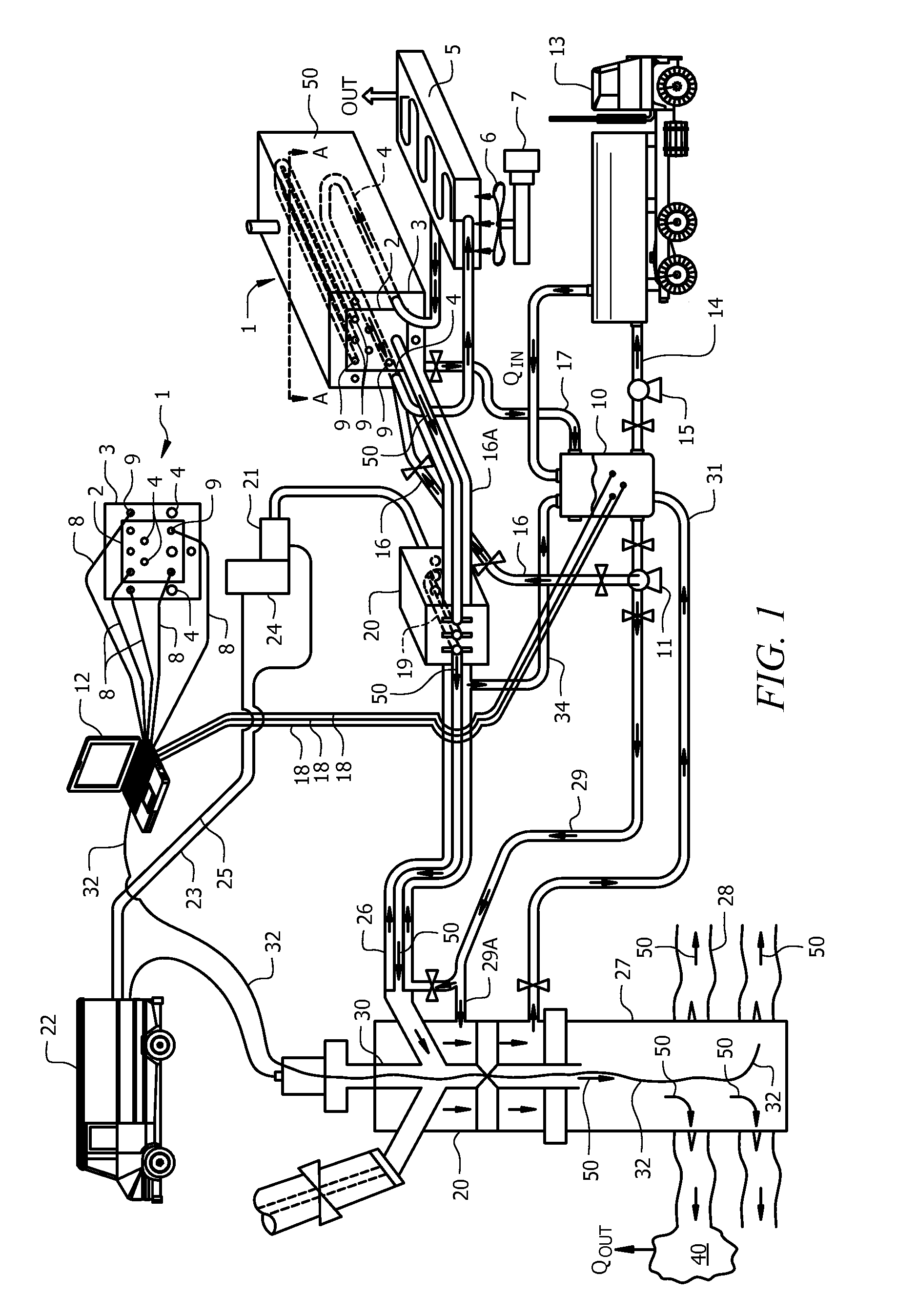
[0036]In the embodiment of FIG. 1, tank 1 holds a reactive fluid 50 and has shroud 3 located around inner tank 2. Many reactive fluids may be used, including but not limited to hydrogen peroxide, hydrazine, monopropellants, hydrogen fluoride, hypergolic fluids (i.e., combustible without an ignition source), acids, bases, alcohols, diesel, propane, liquid natural gas, and combinations thereof. The reactive fluid 50 is preferably stored, monitored, and temperature controlled inside inner tank 2. Located inside tank shroud 3 are heat exchanger ...


PUM


Abstract

The invention relates to methods and apparatuses for the subterranean injection of reactive substances like propellants into wellbores and subterranean reservoirs. These methods and apparatuses controls the temperature of a reactive substance for safe handling at surface and controls the decomposition rate of the substances in the subterranean environment. In addition, these methods and apparatuses provide a means for safe dilution of reactive fluids in the event of a leak or spillage of the reactive substance.

Description

CROSS-REFERENCE TO RELATED APPLICATIONS[0001]This application claims priority to U.S. Provisional Patent Application No. 61 / 045,062, filed on Apr. 15, 2008, which is incorporated by reference herein in its entirety.TECHNICAL FIELD[0002]The present invention is directed to methods and apparatus to inject high energy density substances into subterranean environments where they react. More specifically, this invention is directed to methods and apparatus to inject high energy density fluids like reactive mono-propellants and other hypergolic fluids into subterranean environments through wellbores into the earth.BACKGROUND OF THE INVENTION[0003]When a fluid, such as oil and natural gas, is being produced from a subterranean reservoir through a wellbore the reservoir's ability to produce such fluids is often enhanced by processes that inject fluids and solids from the surface through a wellbore into subterranean reservoirs. There is one field of work that uses these fluids and is known t...

Claims


Application Information

Patent Timeline
Patent Type & Authority Patents(United States)
IPC IPC(8): E21B43/243
CPCE21B43/26E21B43/263E21B43/2607
Inventor SMITH, DAVID RANDOLPH
Owner SMITH DAVID RANDOLPH
Why Eureka
Try Eureka