
System and method for digital parallel frequency fluorometry

a digital parallel frequency and fluorometric technology, applied in the field of analytical chemistry, can solve the problems of large reduction of detector efficiency, long dead time of data collection at a single frequency, and ineffective mixing scheme obtained for modulating the gain of detectors in parallel multifrequency instruments, etc., and achieve the effect of small and less expensive instruments

Active Publication Date: 2012-12-11
I S S USA
View PDF13 Cites 2 Cited by
  • Summary
  • Abstract
  • Description
  • Claims
  • Application Information

AI Technical Summary

Benefits of technology

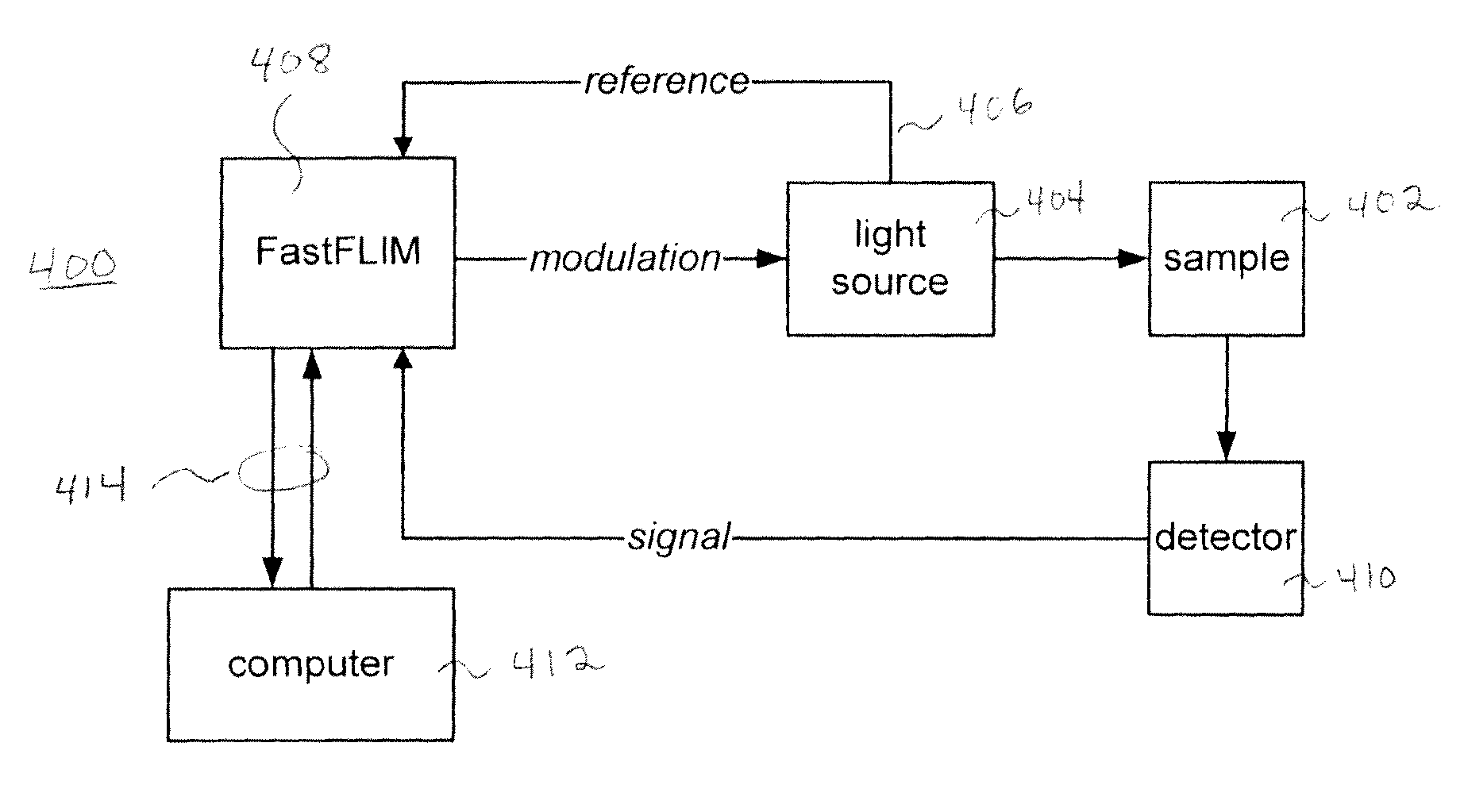
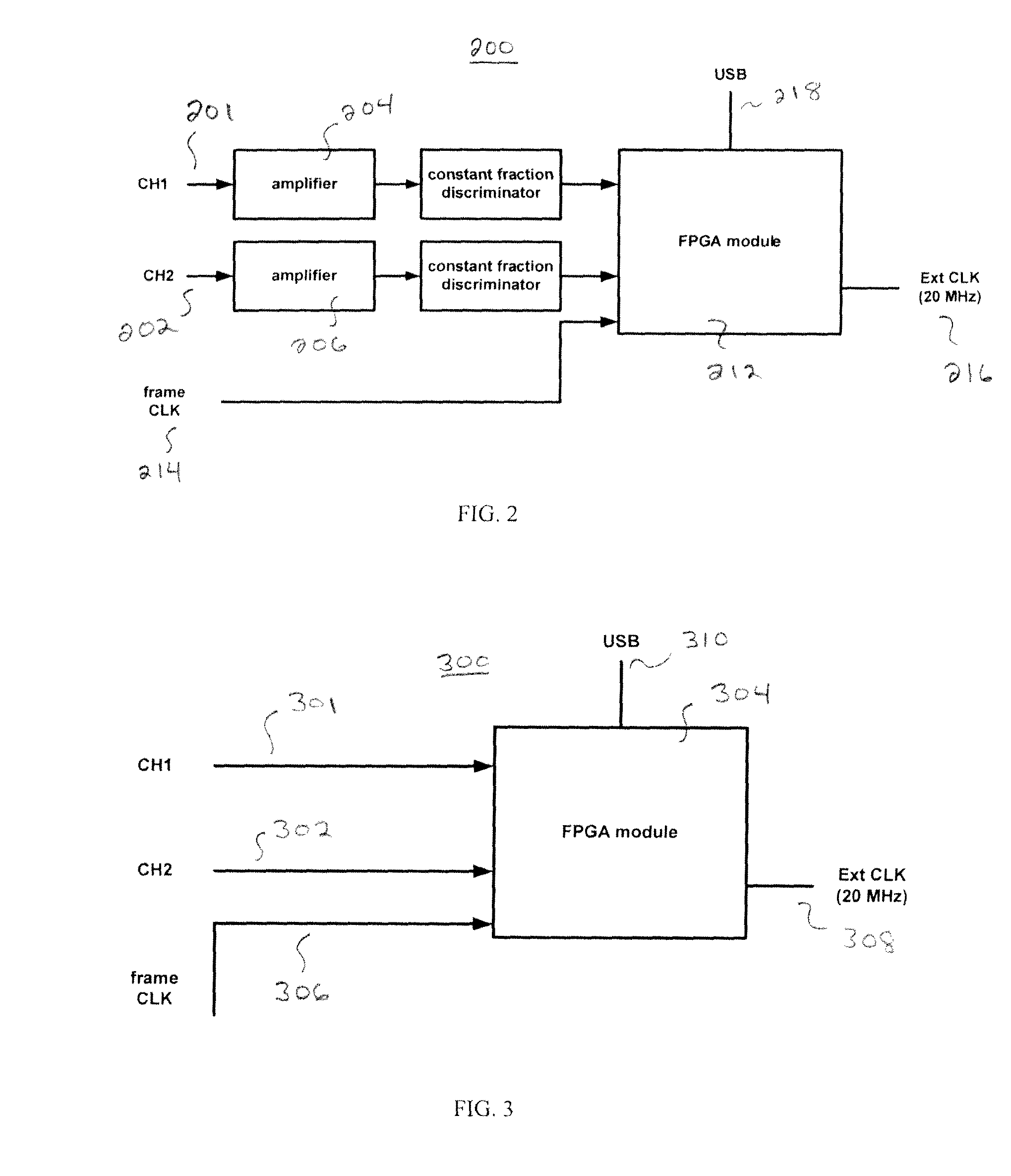
[0033]The illustrative embodiments of the present invention describe a parallel multifrequency phase fluorometer capable of acquiring all of the photons emitted by the sample and therefore provide high sensitivity and fast data collection. Contrary to standard multifrequency phase and modulation fluorometers, the gain of the light detectors is not modulated by using an external frequency generator. Rather, in the illustrative embodiments, heterodyning is performed digitally thus greatly simplifying the amount of electronics components utilized. Because the inventive embodiments do not require the modulation of the gain and / or the signal, virtually any light detectors (PMT, MCP, APD, photodiode) can be equally utilized.
[0035]The digital parallel acquisition scheme presented in the present application provides a digital version of the mixing scheme used in parallel acquisition and, advantageously, samples with 100% duty cycle. In addition, since the embodiments of the present invention use only digital electronics, there is no switching time. Also there is no need to cycle between the sample and the reference. As a consequence of these improvements, the total time of data acquisition for collecting 16 frequencies is reduced form several hundred seconds to about 1 s or less. Since the digital electronics used in the illustrative embodiments of the present invention are very stable, the accuracy of the measurement is increased and the electronic noise is reduced.
[0039]Embodiments of the present invention can be used to build a portable tissue spectroscopy that is for smaller and less expensive instruments than previously known frequency domain instruments. Also, the use of multiple modulation frequencies according to the present invention, instead of one modulation frequency, allows for the design of smaller sensors, which are of extreme interest for infant applications and, in general, for the measurement of hemodynamic parameters in restricted areas.

Problems solved by technology

Although all the harmonic frequencies are measured in parallel, the mixing scheme obtained modulating the gain of the detector in the parallel multifrequency instrument is very ineffective.
In fact, the operation of pulsing the detector gain is equivalent to turning the detector ON for a very brief period, resulting in substantial decrease of the detector efficiency.
For example, the collection of data at a single frequency has a long dead time due to waiting for the electronic to stabilize when the frequency is switched.
However, a disadvantage of the parallel acquisition mode is that the detector is turned ON only for a fraction of time due to the pulse mixing occurring at the detector.
An additional manufacturing problem with this apparatus is that hardware changes must be made to the PMTs voltage divider, which can be quite cumbersome, in order to inject the radio frequency signal.
In addition, direct modulation of the PMT reduces the total collection efficiency of those PMTs, the maximum being 50%.
Also, some detectors, such as avalanche photodiodes (APD) and Microchannel plates (MCP) are not conducive to direct modulation of the gain.
Methods have been devised for applying an external modulation to the signal using a mixer however, the dynamic range is greatly reduced.
Also, some detectors, such as avalanche photodiodes (APD) are not conducive to direct modulation of the gain.
Despite the importance of FLIM, existing FLIM devices are cumbersome to integrate with fluorescence intensity imaging microscopy systems.
Therefore it is not as widely used as fluorescence intensity imaging microscopy.
The time domain devices provide higher resolution for the arrival time of each photon, but also have higher cost.
The frequency domain devices are in general unable to resolve picosecond lifetimes, but cost less.
While the present instrument is suitable for medical research, it cannot be made portable (for sport medicine applications, for instance) as the power utilized by the electronics is too high for the current available batteries to provide power for a reasonable measurement time.

Method used


Image

  • System and method for digital parallel frequency fluorometry
  • System and method for digital parallel frequency fluorometry
  • System and method for digital parallel frequency fluorometry

Examples


Embodiment Construction

[0050]In digital heterodyning the cross-correlation frequency fcc is the difference between the sampling frequency fs utilized to probe the collect the data and the excitation frequency fexc of the light source, that is:

fcc=|fs−fexc|  [7]

[0051]It is convenient to have for fcc a value that is an integer fraction of the sampling frequency; in an illustrative implementation:

[0052]fcc=fs256[8]

[0053]As a result,

[0054]fs=256255⁢fexc[9]

[0055]That is, if the signals of the excitation light fexc waveform and the signal of the sampling frequency waveform are in phase at time t=0, they return in phase after 256 periods of the sampling frequency waveform. This time is also equal to:

[0056]T=1fcc[10]

[0057]In other words, given a set sampling frequency fs, the inverse of the cross-correlation frequency fcc is time the sampling window slides through the entire 255 waveforms of the excitation pulses; these correspond to the number of waveforms of the emission response of the sample.

[0058]The samplin...


PUM

PropertyMeasurementUnit
frequency-aaaaaaaaaa
frequencyaaaaaaaaaa
modulation frequencyaaaaaaaaaa

Abstract

A system and method is provided for improved fluorescence decay time measurement. A digital heterodyning technique is disclosed in which a photon detector is sampled at a rate slightly faster than a digitally pulsed excitation signal. A resulting cross correlation frequency is low enough to be read by inexpensive electronics such as by a field programmable gate array. Phase information in the signal provides correlation with corresponding photon detections.

Description

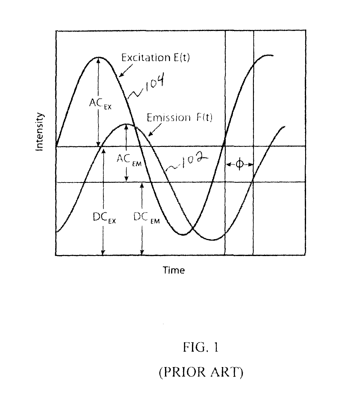
FIELD OF THE INVENTION[0001]The present invention is in the field of analytical chemistry, and particularly relates to fluorescence decay time measurement and frequency domain fluorometry.BACKGROUND OF THE INVENTIONMeasurements of Fluorescence Decay Times[0002]Fluorescence is the light emitted by molecules in solution (or in a solid or gaseous state) following the absorption of radiation. Upon excitation with a short pulse of light of very short duration, the fluorescence emitted by the sample is described by the relationship:I(t)=I0exp−t / τ  [1]where I0 is the intensity of the fluorescence at time t=0 and τ is the time it takes the intensity to decrease to a value e−1 its original value. The value τ is called the “fluorescence decay time”.[0003]In a multi-components environment, the fluorescence is described by the relationship:[0004]I⁡(λ,t)=I0⁢∑i⁢αi⁡(λi)⁢exp-t / τi⁢[2]where the coefficients αi(λi), called the pre-exponential factors and the decay times τi characterize fluorescence de...

Claims


Application Information

Patent Timeline
Patent Type & Authority Patents(United States)
IPC IPC(8): G01N21/64
CPCG01J3/4406G01J3/457G01N21/6408G01N21/6458G01N2021/6423G01N2021/6441
Inventor GRATTON, ENRICOD'AMICO, ENRICO
Owner I S S USA
Learn More