Encephalic insonication

a technology of encephalic insonication and insonication chamber, which is applied in the field of insonication of animal bodies, can solve the problems of only 5% of energy transmission, inability to effectively use encephalic insonication frequency, and pain for patients, and achieve the effects of stimulating vasodilation, stimulating vasodilation, and enhancing perfusion in ischemic tissue surrounding a blood clo

Active Publication Date: 2013-01-15
BOSTON SCI SCIMED INC
View PDF30 Cites 29 Cited by
  • Summary
  • Abstract
  • Description
  • Claims
  • Application Information

AI Technical Summary

Benefits of technology

[0014]The insonication is provided by means of a compact transducer array which is snugly fitted over the head of the patient. The array is mounted on a headpiece which specifically positions the array at a location which not only orients it for insonication of the region of the brain in which blood clots are most encountered (i.e., the circle of Willis and the mid-cerebral artery) but which also locates the array in a region of the skull at which a relatively high ultrasound transmission efficiency is obtained. It is preferably to positioned contralateral to (i.e., on the opposite side of) the side of the head from where the stroke is believed to have occurred. This not only locates the thrombus in the far field of the array, and thus provides a more nearly uniform insonication field, but also removes the heat generated by the array to a location more distant from the thrombus, a region which is often particularly sensitive to increased heat.
[0022]As a further aspect of the invention, we have found that, when used in conjunction with a lytic agent, e.g., t-PA, the energy applied during the initial portion of an active period is more effective in producing lysis than energy delivered later in the active period. Thus, in the present invention, during a given active period, we do not drive the transducers continuously, but repeatedly cycle them “on” and “off” in pairs. In this manner, we have been able to obtain the desired lytic effect of the transducer energy while minimizing the “on” time of the transducers and thus of the power that they generate. This not only reduces the overall energy that must be absorbed by a patient during treatment, but also minimizes local heating and thus further enhances patient comfort and safety. In the preferred embodiment described herein, we use a cycle time on the order of 8 milliseconds. Within each cycle, the transducers are energized for only a portion of the cycle. In the particular embodiment described herein, they are energized for a time on the order of 5% of the cycle time, i.e., approximately 0.4 milliseconds. Further in accordance with the present invention, the transducers are preferably energized in-phase for a portion of the cycle time and are energized out-of-phase for the remaining portion. Preferably, these portions are of equal duration. Due to interference between the two transducer beams, the field created by the two beams covers the desired area but will have spatial peaks and nulls. By driving the transducers alternately in and out of phase, the positions of the peaks and nulls are changed or even reversed, resulting in a time average insonification that is more nearly uniform than that of the individual fields. A further increase in uniformity of insonication of a region of the brain can be achieved by varying the driving frequency of the input to the transducers by a small amount (Preferably less than approximately 10 kHz) during their active periods. The variation may be made continuously through the driving period, or may be made in small discrete steps. This effectively slowly sweeps the residual nulls and peaks of the radiation created by any reverberant standing waves across the brain, and thus helps to provide a more nearly uniform distribution of energy in the region being insonicated.
[0024]Recent studies have indicated that ultrasound, particularly low frequency ultrasound, may enhance perfusion in ischemic tissue surrounding a blood clot. See Suchkova et al., “Effect of 40-kHz Ultrasound on Acute Thrombotic Ischemia in a Rabbit Femoral Artery Thrombosis Model”, Circulation, May 16, 2000, 2296-2301. However, such techniques have not heretofore been applied to treatment of ischemic diseases of the brain. We have determined, however, that ultrasound of the characteristics described herein and applied to the skull as set forth in detail below provides a meaningful beneficial increase in blood flow to under-perfused areas by stimulating vasodilation and enhancing collateral circulation. In particular, we have determined that the method and apparatus of the present invention are of significant benefit in treating acute ischemia, such as stroke, or a chronic ischemia, such as VCI, and can provide desirable, and possibly life-saving, therapy even prior to arrival of the patient at a medical facility. In particular, the transducer array is carried by a headpiece that is quickly, easily and accurately fitted to a patient by paramedics and other emergency medical personnel outside the usual medical facilities to and under field conditions, e.g., at the locus of a patient's stroke, in an ambulance, or the like. The headpiece carries a positioner element that correctly positions the array in relation to the temporal bone of the patient's skull to ensure optimal transmission of the ultrasound energy through the skull into the region to be treated. Thus, even during transit to a medical facility, the patient can thereby begin treatment to alleviate the effects of the is stroke.

Problems solved by technology

However, we have found that such frequencies cannot effectively be used for encephalic insonication because they can be “heard” by a patient undergoing insonication, even though such frequencies are well beyond the normally audible range.
The result can be painful for the patient, and discourages use of the treatment.
However, at 500 kHz the attenuation has increased to 13 dB, resulting in energy transmission of only 5%.
This produces inadequate therapy levels, and would force one to constrain the energy to a more tightly focused beam, thus defeating the concept of regional treatment.

Method used


Image

  • Encephalic insonication
  • Encephalic insonication
  • Encephalic insonication

Examples


Embodiment Construction

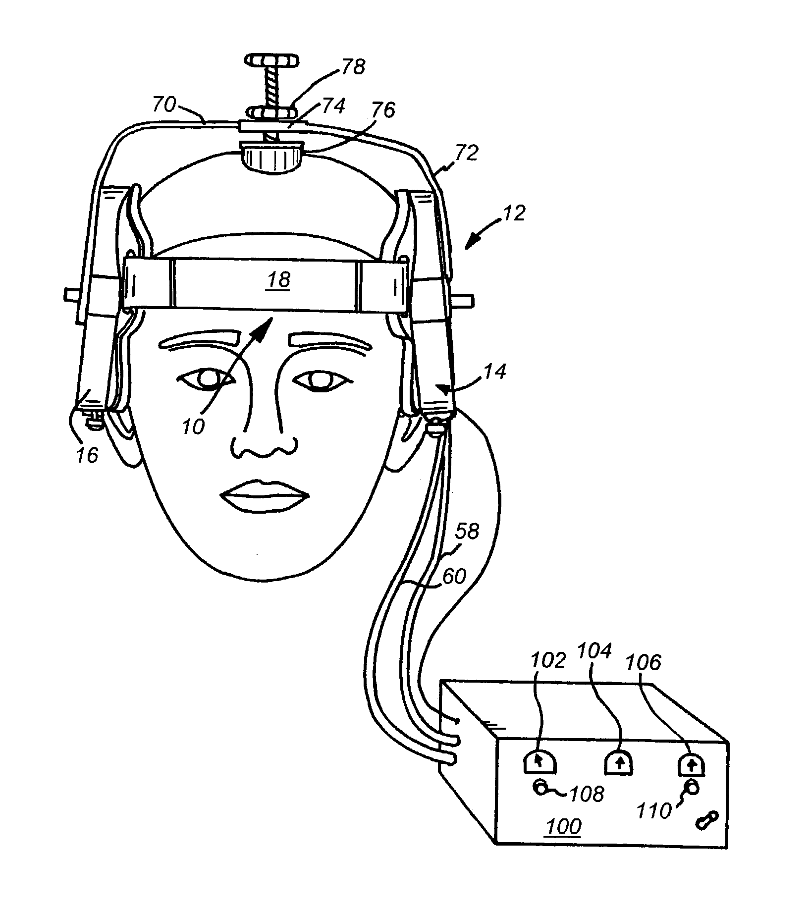
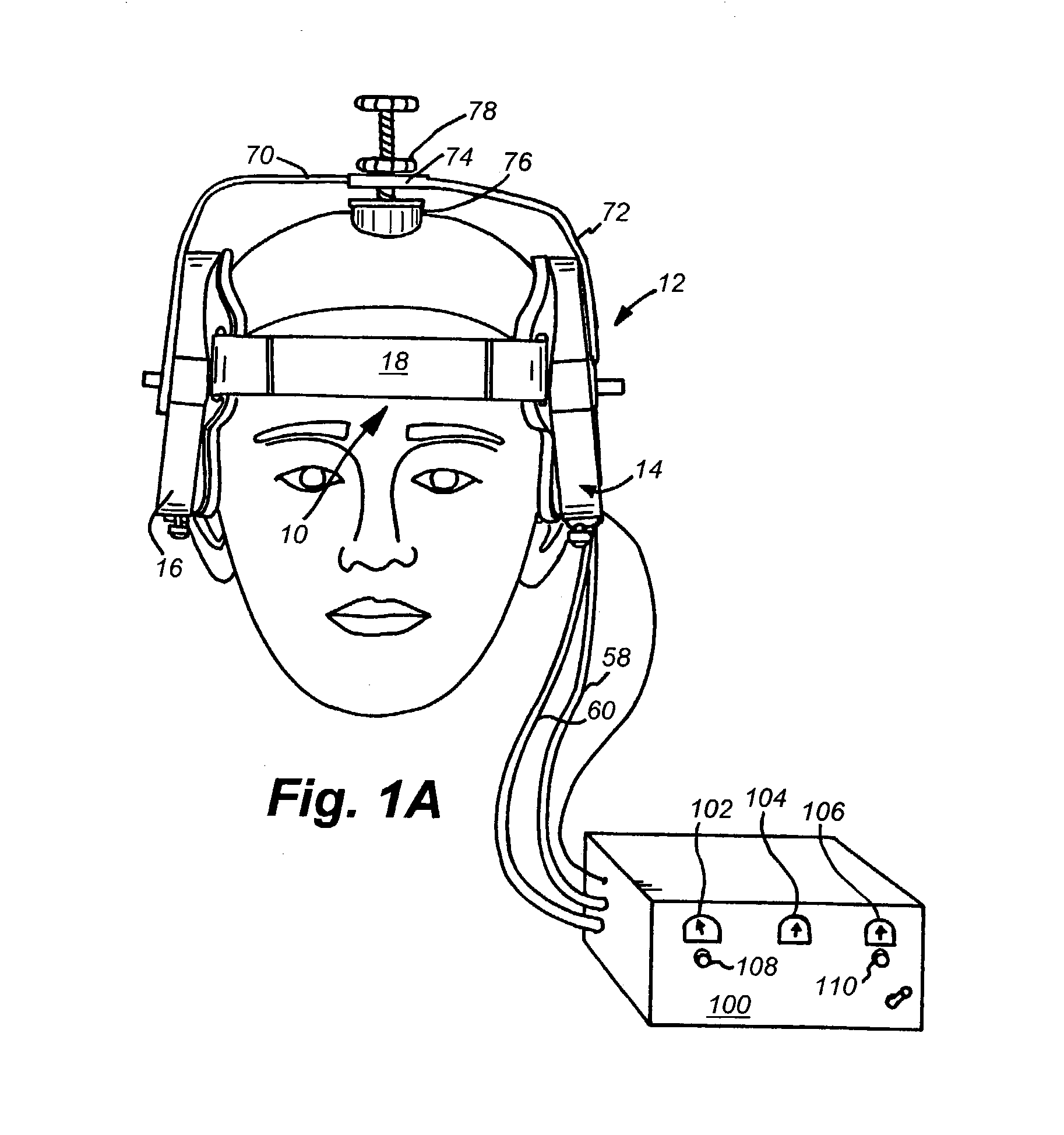
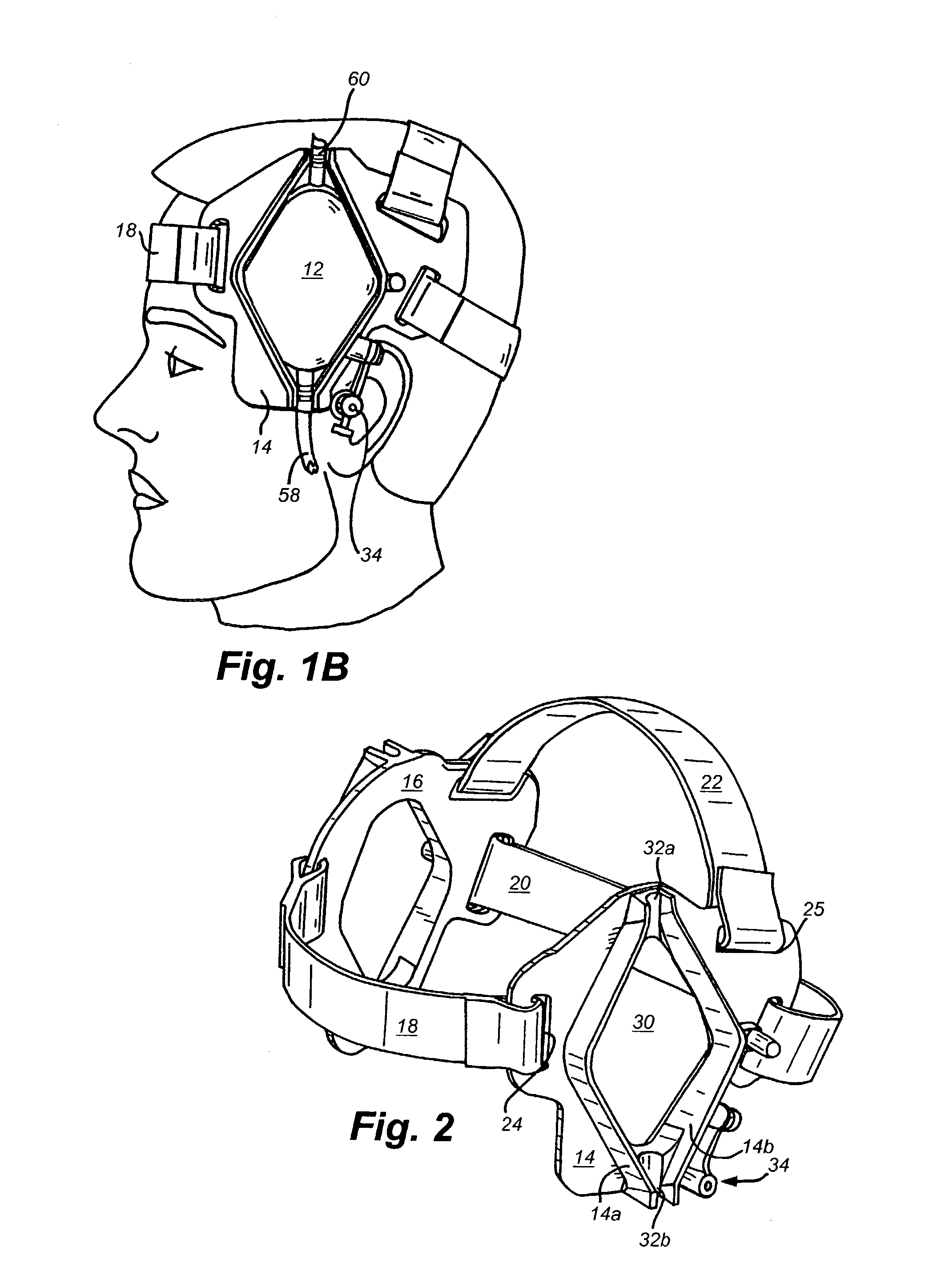
[0040]The following description of the invention will be best understood by concurrent examination of FIGS. 1A and 1B, which are front and side pictorial views of the apparatus of the present invention mounted on the head of a patient for treatment of an embolus in the brain, in conjunction with FIG. 2 which is a view in perspective of only a portion of the headpiece. In FIG. 1, the apparatus of the present invention comprises a head unit having an inner headpiece 10 and an outer driving unit 12. The headpiece 10 comprises a frame 14 connected to lateral and transverse flexible straps 18, 20, respectively. The length of each strap is adjustable to accommodate heads of various sizes. To this end, in the specific embodiment described herein, the opposite end of each strap has a fastening element (e.g., a strip of an interlocking material such as Velcro® fastener material) on opposed faces thereof to enable a technician to quickly slip the strap through a slot such as slots 24 or 25 on...


PUM


Abstract

Apparatus for encephalic insonication, comprising a transducer array configured to safely insonicate a field in a human body of a size comparable to the spatial extent of the array itself. The array comprises a plurality of acoustic transducers arranged in a polygonal configuration and energized in subsets at frequencies between 200 and 400 kHz. A relatively uniform insonication of a field comparable in size to that of significant anatomical regions of the brain is obtained by driving the transducers in each subset in opposed phase relationship during at least part of the interval during which they are active. A pulsed driving scheme enables minimization of heating effects while providing significant therapeutic treatment. The apparatus is useful both with and without additional lytic agents.

Description

BACKGROUND OF THE INVENTION[0001]1. Field of the Invention[0002]The invention relates to insonication of an animal body, and is particularly applicable to insonication of the human brain.[0003]2. Background Information[0004]Among the more significant causes of death or significant disability, stroke and ischemia of the brain are major factors. Stroke is commonly caused by the formation of thrombi, i.e., blood clots formed in the circulatory system of an animal body, including to the arteries, the veins, and the capillary system. When sufficiently large as to effectively occlude a vessel, they can cause heart attack or stroke, dependent on their location. When such thrombi form, it is essential to clear them in the shortest possible time, else death or at least significant damage may ensue. The time to treatment is critical for successful stroke therapy using thrombolytic agents. Only a small percentage (less than 20%) reach a hospital in time to qualify for such treatment.[0005]Thro...

Claims


Application Information

Patent Timeline
Patent Type & Authority Patents(United States)
IPC IPC(8): A61B8/00
CPCA61N7/00A61B2018/00023A61B2018/00321A61B2018/0041A61N2007/0078
Inventor KYLE, ALBERTMASON, MARTIN
Owner BOSTON SCI SCIMED INC
Why Eureka
Try Eureka