Method and apparatus for aerodynamic flow control using compact high-frequency fluidic actuator arrays

a fluid actuator and high-frequency technology, applied in mechanical equipment, air-flow influencers, transportation and packaging, etc., can solve the problems of real challenge in integrating such systems into the actual hardware of aerospace vehicles, and achieve the effects of large divergence angles, uniform air distribution into the engine, and excellent design utility

Active Publication Date: 2013-02-26
RAGHU SURYA
View PDF6 Cites 87 Cited by
  • Summary
  • Abstract
  • Description
  • Claims
  • Application Information

AI Technical Summary

Benefits of technology

[0015]Flow control using the present invention in inlet ducts of airplane engines will permit use of complex inlet geometries suited for positioning the jet engines at locations advantageous for the flight performance of the airplane. The use of compact arrays of the plurality of fluidic actuators of the present invention will prevent flow separating from the interior walls of the inlet duct and thus provide a uniform distribution of air into the engine.
[0016]The compact arrays of the present invention have excellent utility in the design of short diffusers and Vertical or Short Take Off and Landing (V/STOL) aircraft applications. The design of short diffusers involves large divergence angles for the flow. Such large divergence angles need flow control to keep the flow attached to the surfaces of the diffuser walls. The flow control required is accomplished by the utilization of the compact arrays of fluidic actuators of the present invention. Short diffusers increase the efficiency of energy conversion from kinetic energy to pressure energy. One application of such short diffusers is in certain kinds of vertical and short take off and landing aircraft designs.
[0017]These compact fluidic actuators can also be used for noise reduction in jet and rocket engines and the like by modifying the structure of the fluid flow emanating from the exhaust. The main source of aerodynamic noise in jet and rocket engine exhausts is the organized vortical structures emanating from the near-field of the exiting jet. By injecting small amoun

Problems solved by technology

Although most of these devices have demonstrated significant levels of flow control in laboratory scale experiments, integration of such systems into actual hardware of aerospace vehicles have remained a real

Method used


Image

  • Method and apparatus for aerodynamic flow control using compact high-frequency fluidic actuator arrays
  • Method and apparatus for aerodynamic flow control using compact high-frequency fluidic actuator arrays
  • Method and apparatus for aerodynamic flow control using compact high-frequency fluidic actuator arrays

Examples


Embodiment Construction

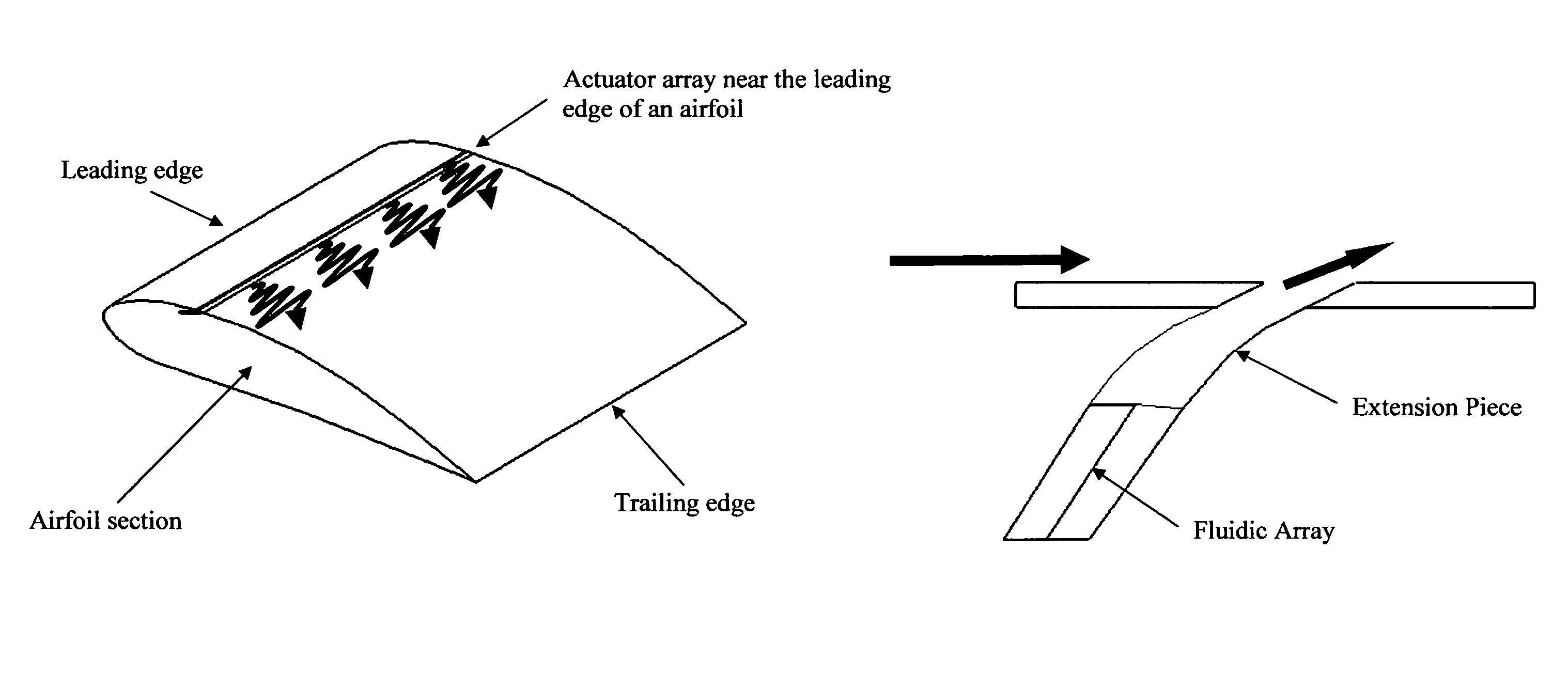
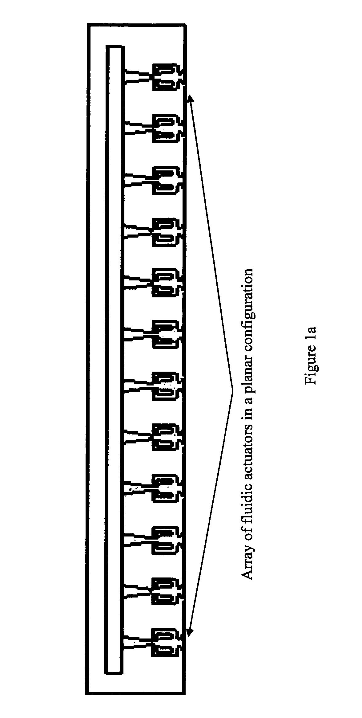
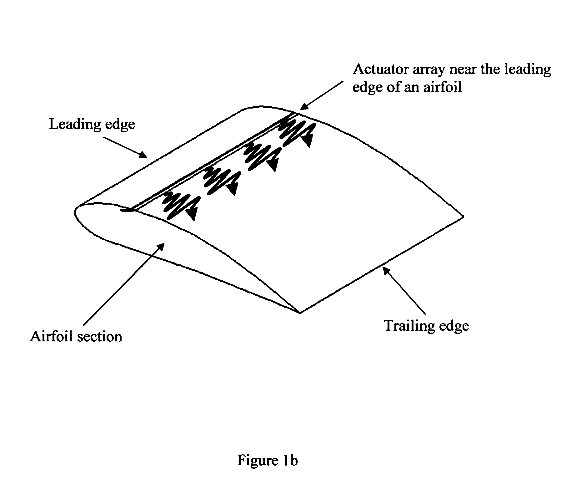
[0031]FIG. 1a shows an array of discrete fluidic oscillators with a common plenum chamber to supply air to all the actuators. Such an array of actuators can be integrated into an airfoil to produce arrays of oscillating jets with frequency in the range of 1-22 kHz and with sweep angles between 20 to 120 degrees. Possible configurations for flow control over an airfoil are shown in FIG. 1b and FIG. 1c. In FIG. 1b, the array is placed closer to the leading edge for separation control at high angles of attack. The oscillating jets exit tangential to the local surface. FIG. 1c illustrates the location of the array for circulation and airfoil wake control. The exact chord-wise position, both for leading edge and trailing edge flow control, depends on the particular airfoil characteristics. Similar flow control schemes can be incorporated in leading edge slats and trailing edge flaps currently used for high-lift configurations to further enhance the performance of such devices.

[0032]With ...


PUM


Abstract

The present invention is directed to the manufacture of and the use of an aerodynamic flow control device having a compact array of a plurality of fluidic actuators in planar, curved, circular and annular configurations. The compact array of fluidic actuators of the invention may be designed to produce oscillating or pulsed jets at the exit ports with frequencies in the range of 1-22 kHz. They may be integrally manufactured along with the wing sections, flaps, tail and rudder of airplane, the inlet or exit geometries of a jet engine. When supplied with a source of fluid such as air, these arrays of actuators produce a set of fluid jets of random phase of high velocity and influence the main stream of air over the subject surface. The beneficial effects of modifying flow using the present invention include increased lift, reduced drag, improved performance and noise reduction in jet engines.

Description

CROSS-REFERENCE TO RELATED APPLICATIONS[0001]This application claims the benefit of the filing date of Provisional Patent application 61 / 274,417 filed on Aug. 17, 2009.BACKGROUND OF THE INVENTION[0002]The aerodynamic design of future aerospace vehicles will be greatly influenced by active flow control (AFC) technologies available for jet engine inlet and exhaust systems, aerodynamic surfaces including high-lift devices, thrust vectoring, weapons-bay cavity flow / acoustics, impingement jet noise reduction, and propulsion devices such as jet engines and rockets. These flow control systems will be used in a variety of flow situations to modify the shear layers and control mixing, energize the boundary layers to control flow separation, produce jet deflections to produce thrust vectoring and to control resonant cavity oscillations. An important aspect of the active flow control technology is the effective strategic deployment of suitable flow actuators. A variety of flow control actuator...

Claims


Application Information

Patent Timeline
IPC IPC(8): B64C21/04
CPCB64C21/04F15D1/008B64C2230/18B64C2230/04Y02T50/166Y02T50/10
Inventor RAGHU, SURYA
Owner RAGHU SURYA
Why Eureka
Try Eureka