
MEMS based pyroelectric thermal energy harvester

a pyroelectric and thermal energy harvesting technology, applied in the direction of generators/motors, nuclear engineering, electric discharge tubes, etc., can solve the problems of low energy conversion efficiency of thermal to electrical energy conversion techniques (thermoelectric, piezoelectric and pyroelectric) and inherent limitations of the conversion technology itself, so as to achieve large reductions and high-quality electrical energy

Inactive Publication Date: 2013-08-27
UT BATTELLE LLC
View PDF26 Cites 24 Cited by
  • Summary
  • Abstract
  • Description
  • Claims
  • Application Information

AI Technical Summary

Benefits of technology

[0017]Desired overall energy conversion efficiencies in the range of 20-30% or greater are sought, and efficiencies up to 80% of the Carnot efficiency limit are obtainable with scaled arrays (up to 106 converter elements). As a result, the subject invention may provide large reductions in waste heat production and subsequent cooling requirements, together with the generation of high quality electrical energy from a wide range of waste heat sources.

Problems solved by technology

Presently contemplated thermal to electrical energy conversion techniques (thermoelectric, piezoelectric and pyroelectric) all suffer from low energy conversion efficiencies, limited partly by the Carnot efficiency, but also by the inherent limitations of the conversion technologies themselves.
Pyroelectric converters remain relatively unexplored, as early attempts to model and fabricate converters based on pyroelectric operating principles gave uneconomically low conversion efficiencies (0.1-2%).
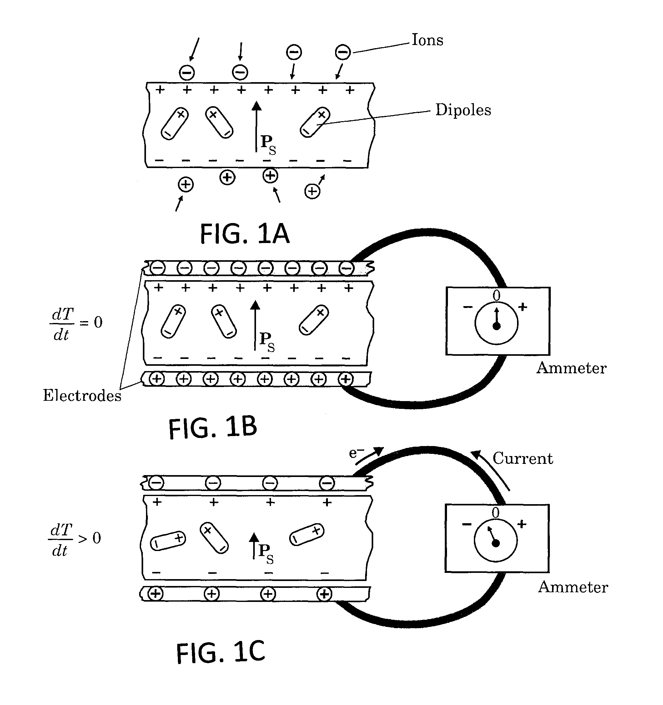
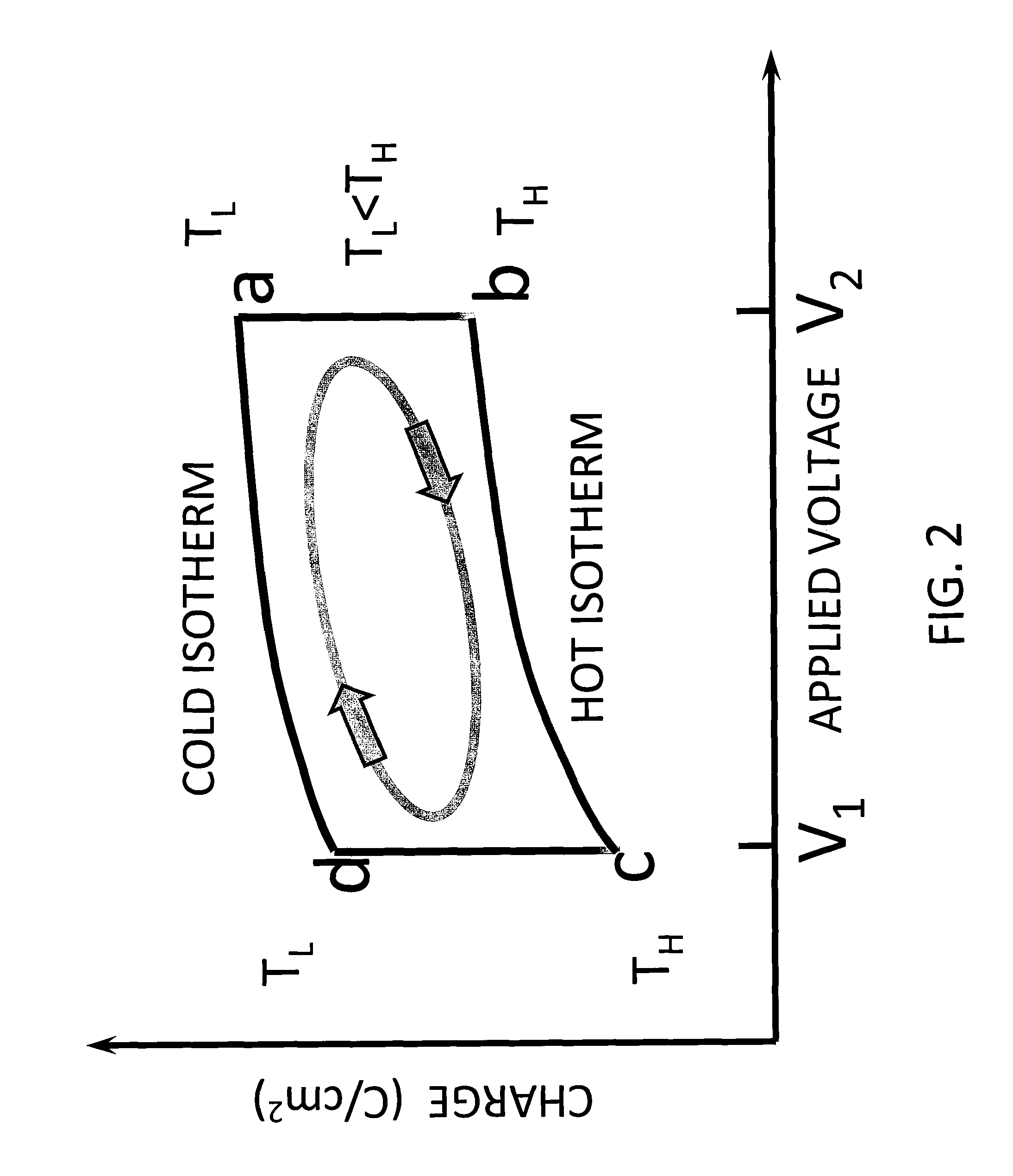
The quasi-isothermal cycle used in the simple prior art energy harvester shown in FIGS. 1A-1C is very inefficient and, as a result, produces very little power.
Prior attempts to use this technique to generate electricity have suffered from low energy conversion efficiencies due to the low operating frequencies (p in Equation 1), large thermal mass capacitor systems with relatively low breakdown strengths (i.e. low voltage differences, V2−V1) and low thermal conductivities (leading to low ΔT / Δt) and hence low ΔQ / ΔT.

Method used


Image

  • MEMS based pyroelectric thermal energy harvester
  • MEMS based pyroelectric thermal energy harvester
  • MEMS based pyroelectric thermal energy harvester

Examples


example 1

[0063]According to preliminary proof of concept testing, a traditional pyroelectric capacitor is fabricated from a polyvinylidene difluoride-trifluoroethylene copolymer (PVDF-TrFE or copolymer) based capacitor. This material includes a relatively high pyroelectric coefficient and dielectric strength and ease of fabrication using current wet chemical and wafer processing equipment and techniques.

[0064]According to this embodiment, the pyroelectric capacitors are preferably fabricated by sputtering Al electrodes onto each side of a 25 μm thick, electrically poled copolymer film. Electrical leads may be attached to the capacitor electrodes using silver based electrically conductive past. The measured capacitances for several of these thin film pyroelectric capacitors ranged from approximately 140 pF up to 1 nF. A 140 pF capacitor generates currents in the 10-15 nA range when exposed to changes in temperature of 15-20° C. Higher conversion efficiencies are achievable through adjustments...

example 2

[0065]According to further proof of concept testing, a pyroelectric capacitor test structure is fabricated from low thermal expansion SiO2, higher thermal expansion Al, and much higher thermal expansion SU-8.

[0066]FIG. 10A-10G show a series of fabrication schematics starting with an Si bare wafer 200 in FIG. 10A. FIG. 10B shows a PE-CVD deposit SiO2 thin film 210, resulting in SiO2 / Si layers. FIG. 10C shows an e-beam deposit of Al thin film 220 resulting in Al / SiO2 / Si layers. FIG. 10D represents a front side lithographic patterning of the structure. FIG. 10E shows an etching of the Al layer 220 and SiO2 layer 210. FIGS. 10F and 10G show backside photolithographic patterning and backside etching of the Si layer 200 to release the biomorphic cantilever structure, respectively.

[0067]The above construction technique is illustrative and is particularly suited to fabrication of test structures and may be adjusted depending on the desired pyroelectric capacitor materials and configuration....

example 3

[0068]According to one preferred embodiment, the fabrication steps leading to the fabrication of a cantilevered pyroelectric capacitive device based on the pyroelectric material aluminum nitride (AIN) is shown schematically in FIG. 11A-H. The AIN material has a lower pyroelectric coefficient than that of the PVDF-TrFE copolymer, but is easier to fabricate into cantilever structures using available processing equipment. A base 100 mm Si wafer 200 is shown in FIG. 11A. The first step in the fabrication of the cantilever structure according to this embodiment uses a 10 μm thick PECVD deposited silicon dioxide layer 260, as shown in FIG. 11B.

[0069]FIG. 11C shows the first photolithography step wherein a 100 nm titanium (Ti) layer 270 is deposited and patterned, and acts as the bottom electrode of the capacitor. Next, as shown in FIG. 11D, the AIN dielectric layer 280 is deposited. FIG. 11E shows the subsequent second photolithography step where the top Ti capacitor electrode layer 290 i...


PUM


Abstract

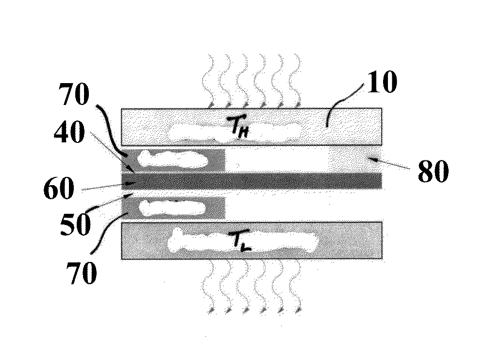
A pyroelectric thermal energy harvesting apparatus for generating an electric current includes a cantilevered layered pyroelectric capacitor extending between a first surface and a second surface, where the first surface includes a temperature difference from the second surface. The layered pyroelectric capacitor includes a conductive, bimetal top electrode layer, an intermediate pyroelectric dielectric layer and a conductive bottom electrode layer. In addition, a pair of proof masses is affixed at a distal end of the layered pyroelectric capacitor to face the first surface and the second surface, wherein the proof masses oscillate between the first surface and the second surface such that a pyroelectric current is generated in the pyroelectric capacitor due to temperature cycling when the proof masses alternately contact the first surface and the second surface.

Description

GOVERNMENT RIGHTS[0001]This invention was made with government support under Contract No. DE-AC05-00OR22725 awarded by the U.S. Department of Energy. The government has certain rights in the invention.FIELD OF THE INVENTION[0002]The present invention relates to a pyroelectric thermal energy harvesting device.BACKGROUND OF THE INVENTION[0003]Industry, worldwide, discharges over 100×1012 joules (TJ) annually of low-grade waste heat (10° C. to 250° C.) from electric power stations, pulp and paper mills, steel and other metal foundries, glass manufacturers and petrochemical plants. A technology to recover or convert this low-grade waste heat to usable electricity could save industrial sectors tens of millions of dollars annually, through increased process efficiencies and reduced fuel costs, while substantially reducing greenhouse gas emissions. Other opportunities also exist for active cooling and electrical power generation for sensor systems on much smaller scales, such as on-chip ac...

Claims


Application Information

Patent Timeline
Patent Type & Authority Patents(United States)
IPC IPC(8): H02N10/00
CPCH01L37/02H10N15/10
Inventor HUNTER, SCOTT R.DATSKOS, PANAGIOTIS G.
Owner UT BATTELLE LLC
Learn More