Systems and methods for gas separation using high-speed induction motors with centrifugal compressors

a technology of gas separation and high-speed induction motor, which is applied in the direction of separation process, hydrogen separation using solid contact, machines/engines, etc., can solve the problems of high system pressure pulsation, adsorption process, and low product recovery rate of many cryogenic processes, and achieve optimal efficiency

Active Publication Date: 2013-09-10
PRAXAIR TECH INC +1
View PDF33 Cites 58 Cited by
  • Summary
  • Abstract
  • Description
  • Claims
  • Application Information

AI Technical Summary

Benefits of technology

[0011]The present invention relates to the application of high-speed induction motors designed for variable-speed operation used in adsorption systems, such as PSA or VPSA systems. Designs incorporating such motors can operate at optimal efficiency by allowing for the acceleration or deceleration of system apparatus at rates equal to or exceeding the cycle times (e.g., 35 seconds or less) of current newer PSA and VPSA systems and processes. The present invention more particularly relates to gas separation processes and systems such as PSA or VPSA adsorption systems having at least one vessel containing at least one adsorbent bed therein. The adsorbent bed includes at least one adsorbent material. In some embodiments, at least one adsorbent bed is cyclically pressurized by at least one feed compressor and sometimes evacuated by at least one vacuum compressor, with at least one of the at least one feed compressor or the at least one vacuum compressor being a centrifugal compressor driven by an associated high-speed induction motor designed for variable high-speed operation. In such embodiments, the compressor that is not a centrifugal compressor can be a rotary-lobe blower driven by the induction motor. In some embodiments of the present invention, the adsorbent bed is cyclically pressurized by at least one feed centrifugal compressor driven by an associated high-speed induction variable-speed motor and, evacuated by at least one vacuum centrifugal compressor driven by an associated high-speed induction variable-speed motor. More specifically and in accordance with the present invention, the centrifugal feed compressor(s) and / or centrifugal vacuum compressor(s) are driven by direct drive high-speed induction motors for variable-speed operation such that the compressor and high-speed induction motor combination(s) can accelerate from low-speed to high-speed and decelerate from high-speed to low-speed in rapid rates required by shorter cycle times of current PSA or VPSA systems and processes.
[0012]Use of variable-speed control high-speed induction motors in accordance with the present invention allows for an order of magnitude improvement over conventional low-speed induction motor / gearbox systems in their ability to accelerate and slow down the centrifugal compressor in a PSA or VPSA process. Using high-speed induction motors in accordance with the invention allows for the elimination of the necessity for gearboxes and thus likewise allows for the elimination of the necessity of lube oil systems. The centrifugal compressor(s) can thus be supported on oil free bearings. Furthermore, in some embodiments, the proposed drive systems of the present invention are expected to be more efficient by over 7 percentage points with the elimination of gear and bearing oil friction losses, lube oil system losses, and an improved ability to lead / lag power.

Problems solved by technology

Adsorption processes, however, typically have lower product recovery than many cryogenic processes.
Rotary-lobe blowers, however, create strong pressure pulsations in the system.
Without proper mitigation, pressure pulsations from rotary-lobe blowers are known to cause severe structural damage in downstream process equipment.
Although pulsation damper vessels are normally used with rotary-lobe blowers, they do not eliminate the mismatch completely, and a considerable pressure pulsation level is always present in the system.
As the PSA or VPSA cycle pressure deviates from the design pressure condition of a fixed-speed centrifugal compressor, the stage efficiency deteriorates substantially, especially when operating at pressure ratios close to 1 (choking).
This results in increased average power consumption and a deterioration of the overall average compressor efficiency over the PSA or VPSA cycle.
Still, this technology could not be successfully employed in the past.
The use of conventional fixed-speed centrifugal compressors with and without IGVs is not ideal because of their limited operating range.
A conventional variable-speed centrifugal compressor can have an improved operating range and improved energy savings over the use of IGVs with a reduction in flow, but is unable to rapidly adapt to the transient flow conditions of the PSA or VPSA cycle (due to the large inertias of the gears and large slow running IM rotor).

Method used


Image

  • Systems and methods for gas separation using high-speed induction motors with centrifugal compressors
  • Systems and methods for gas separation using high-speed induction motors with centrifugal compressors
  • Systems and methods for gas separation using high-speed induction motors with centrifugal compressors

Examples


example 1

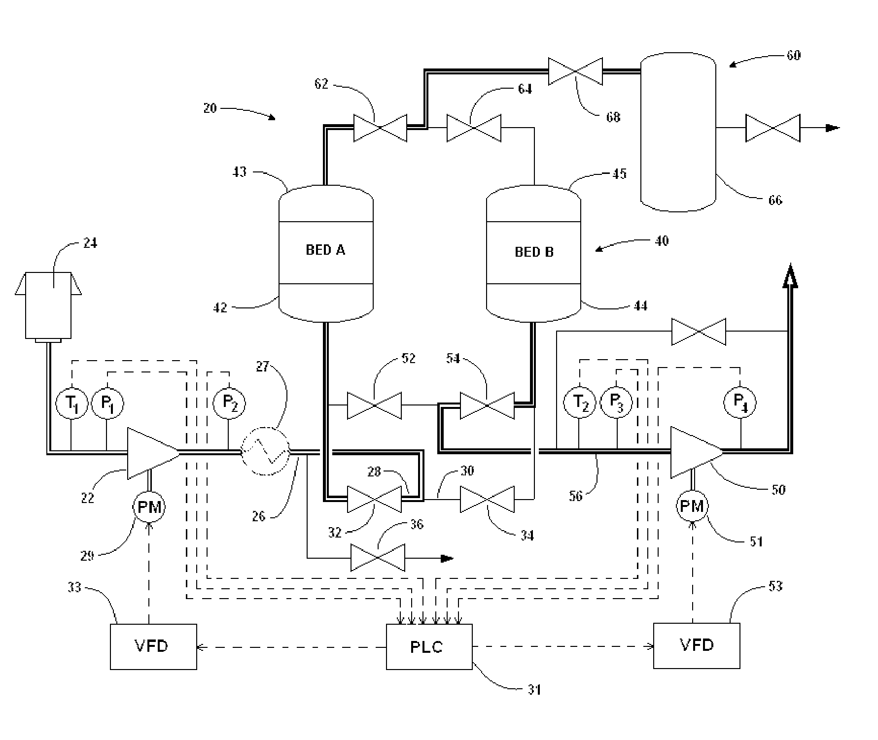
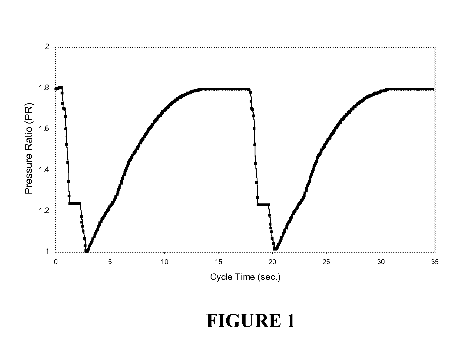
[0059]FIG. 8 is a graphical representation of an exemplary ideal feed compressor response over a typical VPSA cycle. With reference again to FIG. 5 and to FIG. 8 for example, at any instant in time during a VPSA cycle, temperature T1 pressures P1 and P2, temperature T2, and pressures P3 and P4 are measured via a typical pressure transducer or transmitter and recorded in the plant PLC 31. Specifically and for purposes of illustration, looking at the feed compressor 22 during a rising pressure feed step (point A on FIG. 8), the control system calculates the pressure ratio (PR) across the feed machine by dividing P2 over P1. Using this calculated pressure ratio and inlet temperature T1, the control system PLC 31 then determines the motor / compressor operating speed using the compressor performance map and resulting best efficiency line that was generated for T1 as illustrated at point A (in this case, the motor / compressor operating speed is approximately 67% full speed) on FIG. 7. This ...

example 2

[0060]During a constant pressure feed with product make step (see for example point B on FIG. 8), inlet temperature T1 and updated pressure ratio across the feed machine obtained by dividing P2 over P1 serve as inputs to determine the motor / compressor operating speed using the compressor performance map and resulting best efficiency line that was generated for the updated T1 as illustrated at point B (100% full speed) on FIG. 7. This information is then communicated to VFD 33 to direct compressor 22 and motor 29 to operate at such speed. Similar determinations and communications are likewise accomplished with respect to centrifugal vacuum compressor 50 and high-speed IM 51.

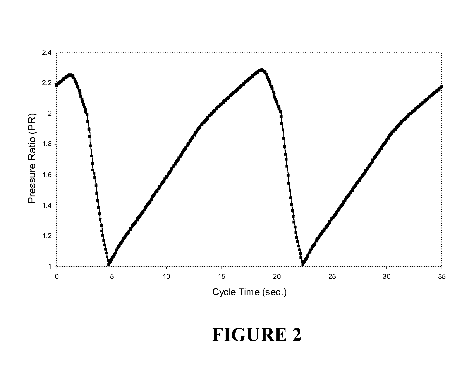
[0061]In general, the pressure ratio across the compressor fluctuates in response to system pressure changes (such as occurs during pressuriziation and evacuation of the adsorbent bed(s)). The speed of the compressor is continuously varied from 100% design speed to a substantially lower speed (e.g., 40% is the typ...


PUM

PropertyMeasurementUnit
frequencyaaaaaaaaaa
adsorptionaaaaaaaaaa
speedaaaaaaaaaa

Abstract

Systems and processes are provided for gas separation using high-speed induction variable-speed motors to accelerate and decelerate centrifugal compressors suitable for use in pressure swing adsorption (PSA) or vacuum pressure swing adsorption (VPSA) processes.

Description

TECHNICAL FIELD[0001]The present invention generally relates to gas separation processes and systems using high-speed induction motors. More specifically, this invention is directed to the use of induction motors with variable-frequency motor speed control and centrifugal compressors to pressurize and / or evacuate adsorbent vessels within an adsorption type gas separation systems.BACKGROUND OF THE INVENTION[0002]Separations of a gas from admixture with other gases are important industrial processes. In such processes the objective may be either to obtain a product gas enhanced in a particular gas or from which that particular product gas has an undesired constituent removed therefrom. For example, there are commercial scale processes to separate air into its component gases to obtain nitrogen, oxygen, and argon and for air prepurification processes to pretreat the air prior to use in other processes such as the cryogenic separation of air into its component gases.[0003]More specifica...

Claims


Application Information

Patent Timeline
Patent Type & Authority Patents(United States)
IPC IPC(8): B01D59/26
CPCB01D53/0446B01D53/047C01B3/56F04D27/0261B01D53/0476B01D53/053B01D2256/12B01D2257/102Y02B30/70Y02P20/10
Inventor MANNING, MICHAEL S.ROSINSKI, ANDREW C.O'CONNOR, GERALD THOMASBELANGER, PAUL WILLIAM
Owner PRAXAIR TECH INC
Why Eureka
Try Eureka