Internal combustion engine and supercharger

a supercharger and internal combustion engine technology, applied in the direction of machines/engines, liquid fuel engines, electric control, etc., can solve the problems of no longer controlling the power output of the engine, reducing the air temperature of compressed air delivered to the engine, etc., to achieve efficient supply of varying amounts of air to the engine, improve the power-to-weight ratio of the engine, and drive variable loads more efficiently

Active Publication Date: 2013-09-24
HANSEN ENGINE
View PDF74 Cites 27 Cited by
  • Summary
  • Abstract
  • Description
  • Claims
  • Application Information

AI Technical Summary

Benefits of technology

[0013]The invention includes the method of supplying power to a power user, such as motor vehicles, pumps, and electric generators. An engine is drivably connected to the power user which imparts a load on the engine. An air supply from a supercharger is directed to the engine that can range selectively from below through above atmospheric pressure in varying amounts responsive to the power requirements of the engine. The rate of flow of air to the engine is varied selectively from below through above the naturally aspirated rate of flow of air to the engine. An amount of fuel is introduced in the air in the intake manifold or in the combustion chamber at the proper time to meet the power or load requirements of the engine and can be controlled to provide proper combustion and emissions performance. The supercharger is operable to expel a first portion of the volume of uncompressed air generated by the supercharger to atmosphere, and direct a second portion of the volume of air generated by the supercharger to the engine. The first portion of air, expelled to atmosphere, is controlled to selectively vary the volume or rate of flow of the second portion of the air directed to the engine. The first portion of air cools the rotors and housing as the air transfers heat generated by the previous compression of air by the rotors. This reduces the temperatures of the second portion of air directed to the engine.
[0014]An object of the invention is to improve the power to weight ratio of internal combustion engines. Another object of the invention is to combine a supercharger and a four stroke internal combustion engine to improve the engine's portability and reduce its size and weight for a given maximum power rating. A further object of the invention is to combine an internal combustion engine and a positive displacement air supercharger having the ability to efficiently adjust boost air pressure and air mass flow to the engine over the engine operating range to increase the fuel efficiency of the engine and / or alter the engine exhaust emissions.

Problems solved by technology

In a second operation or case the supercharger varies its displacement to provide more than the engine cycle displacement, and the throttle mechanism is wide open and is no longer controlling the engine power output.
In this case, the uncompressed excess air discharged to atmosphere results in internal cooling of the supercharger components and lowers the air temperature of compressed air delivered to the engine.

Method used


Image

  • Internal combustion engine and supercharger
  • Internal combustion engine and supercharger
  • Internal combustion engine and supercharger

Examples


second embodiment

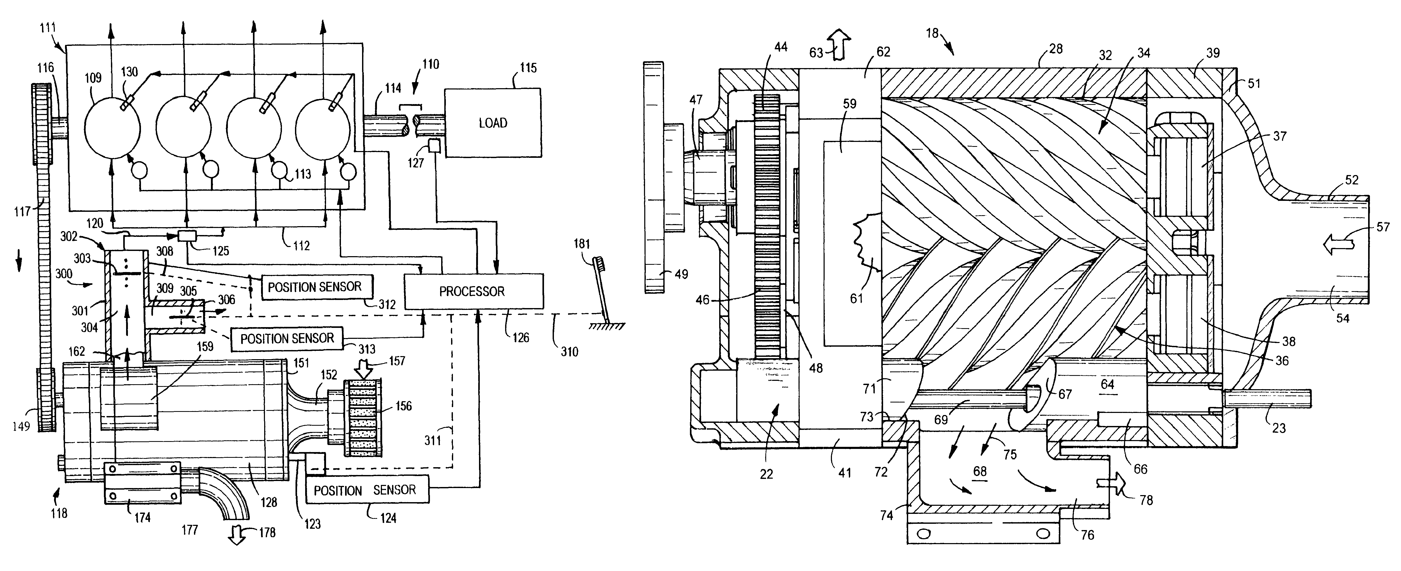
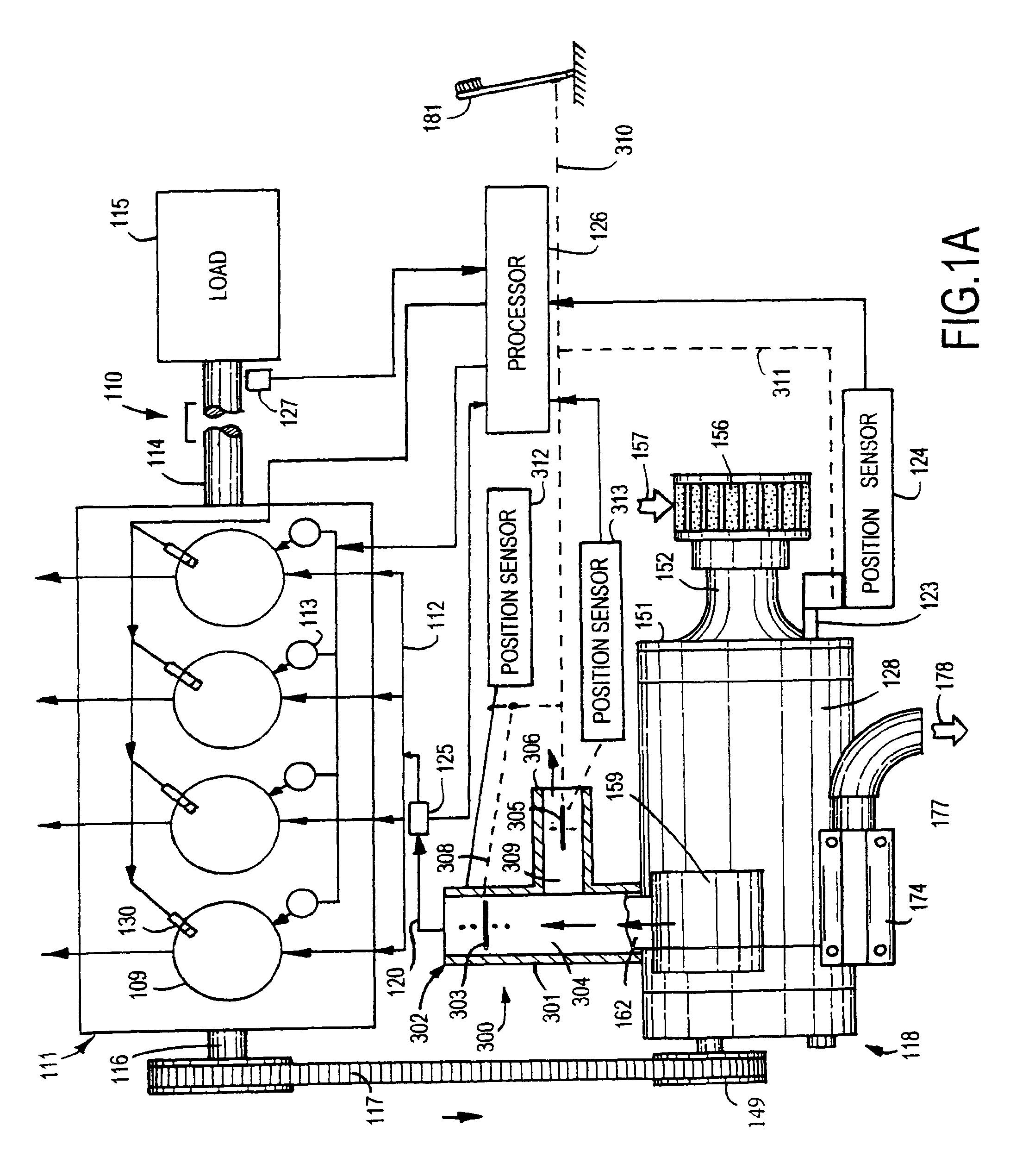
[0044]the supercharged internal combustion power unit 110, shown in FIG. 1A, includes conventional internal combustion engine 111 having a drive shaft 114 connected to a load 115, such as an electric generator, water pump, or vehicle drive system. A supercharger 118 driven by engine 111 is controlled with a processor 126 and actuator 124 operable to operate engine 111 during power changes of the load. Engine 111 can operate at varying speeds to accommodate a load, such as an electric generator. The parts of supercharger 118 that correspond to the parts of supercharger 18 have the same reference numbers with the prefix 1. The engine control system of the second modification shown in FIG. 1A employs a progressive sequential mechanical linkage without electronically controlled actuators. In sequence of increasing power levels, the progressive sequential mechanical linkage first opens throttle plate 303 progressively until fully open, then moves valve member 305 from fully open to fully...

fifth embodiment

[0054]supercharger 618 of the invention, shown in FIG. 14, is operatively driven with an internal combustion engine 611 having cylinders, an air intake manifold 612, fuel injectors 613, ignition igniters 630 and a power output drive shaft 614. Shaft 614 is operably connected to a load 615. Load 615 is an apparatus such as an electric generator, a pump, a vehicle drive system or a machine for receiving power from engine 611. A front drive shaft 616 of engine 611 is connected to a power transmission 617 that drives supercharger 618. Engine 611 is a conventional internal combustion engine. Air is delivered from supercharger 618 into a tubular housing 601 coupled to manifold 612 with tube 620. Supercharger 618 is connected to an air control apparatus 600 to direct all or a portion of the air to intake manifold 612. A heat exchanger (not shown) similar to heat exchanger 419 of FIG. 2 may be installed between housing 601 and intake manifold 612 if desired. An air mass flow sensor 625 coup...

sixth embodiment

[0056]supercharger 718 of the invention, shown in FIG. 14A, is operatively driven with an internal combustion engine 711 having cylinders, an air intake manifold 712, fuel injectors 713, ignition igniters 730 and a power output shaft 714. A load 715 is coupled to shaft 714. The parts of supercharger 718 that correspond to supercharger 618 shown in FIG. 14 have the same reference numbers with the prefix 7 in lieu of prefix 6 and are incorporated herein by reference. The throttle valve 702, valve 708, and control shaft 723 are mechanically connected with progressive sequential linkage 709 to foot pedal 781. Linkage 709 acts sequentially to first operate valve 702, then valve 708, and then shaft 723 independently of processor 726. Valve position sensors 705, 710 and 724 on valves 702, 708, and shaft 723 also report to processor 726 to assist the transient response of the engine in controlling the injection of fuel into the engines cylinders and ignition of the air fuel mixture in the c...


PUM


Abstract

An internal combustion engine drivably connected to a variable displacement and variable internal compression ratio supercharger that supplies varying amounts of air to the engine air intake manifold that can range selectively from below through above atmospheric pressures responsive to the power requirements of the engine. The supercharger has a pair of rotors concurrently driven by the engine to move air to the engine. A slide assembly associated with screw rotors is movable with a controller relative to the rotors to bypass air to atmosphere and regulate the amount of air and pressure of the air above atmospheric pressure compressed by the screw rotors to the engine to increase the engine's efficiency. When operating at part-load unboosted, a throttle valve is operable to control the air mass flowing to the air intake manifold below atmospheric pressure to control the power of the engine.

Description

CROSS REFERENCE TO RELATED APPLICATION[0001]This application is a continuation-in-part of U.S. application Ser. No. 12 / 587,800 filed Oct. 14, 2009.FIELD OF THE INVENTION[0002]The technology of the invention relates to internal combustion engines equipped with superchargers for supplying air to engines with intake manifolds that can range selectively from below through above atmospheric pressure conditions according to the requirements of the engines to increase efficiency and performance of the engines.BACKGROUND OF THE INVENTION[0003]Air displacement devices are used to increase the supply of air and fuel to internal combustion engines to boost engine horsepower. An example of an air displacement device is the “Roots blower” shown by P. H. Roots in U.S. Pat. No. 30,157 and G. Scheerer in U.S. Pat. No. 2,201,014. Each of these devices has a belt-driven shaft that drives two close-clearance rotors. The rotating rotors during each rotation sweep out a specific volume of air to an air ...

Claims


Application Information

Patent Timeline
Patent Type & Authority Patents(United States)
IPC IPC(8): F02B33/44F02B33/00F01C1/16F04C2/00F04C18/00
CPCF01C11/008F02B33/38F02B33/44F02D23/005F04C18/16F04C28/12F02B29/0425F02B39/04F02D41/0007Y02T10/144Y02T10/17Y02T10/12Y02T10/40
Inventor HANSEN, CRAIG N.CROSS, PAUL C.
Owner HANSEN ENGINE
Why Eureka
Try Eureka