Method and system for multiplexer waveguide coupling
a technology of multiplexer and waveguide, applied in the direction of optical multiplex, electrical equipment, instruments, etc., can solve the problems of high coupling loss at the coupling interface, high packaging cost of the integrated optical circuit, and difficulty in fabricating these components using standard planar waveguide technology
- Summary
- Abstract
- Description
- Claims
- Application Information
AI Technical Summary
Benefits of technology
Problems solved by technology
Method used
Image
Examples
first embodiment
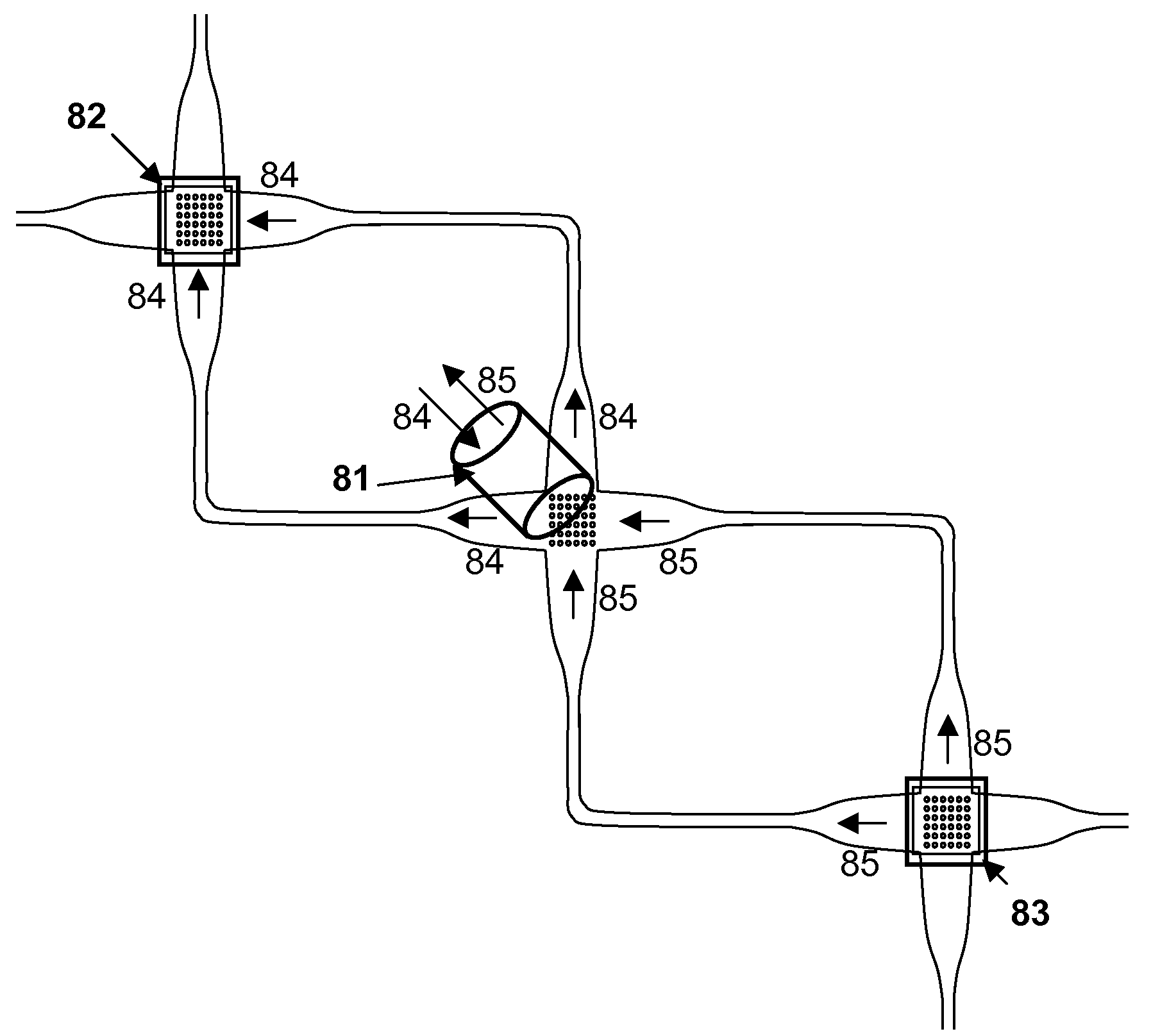
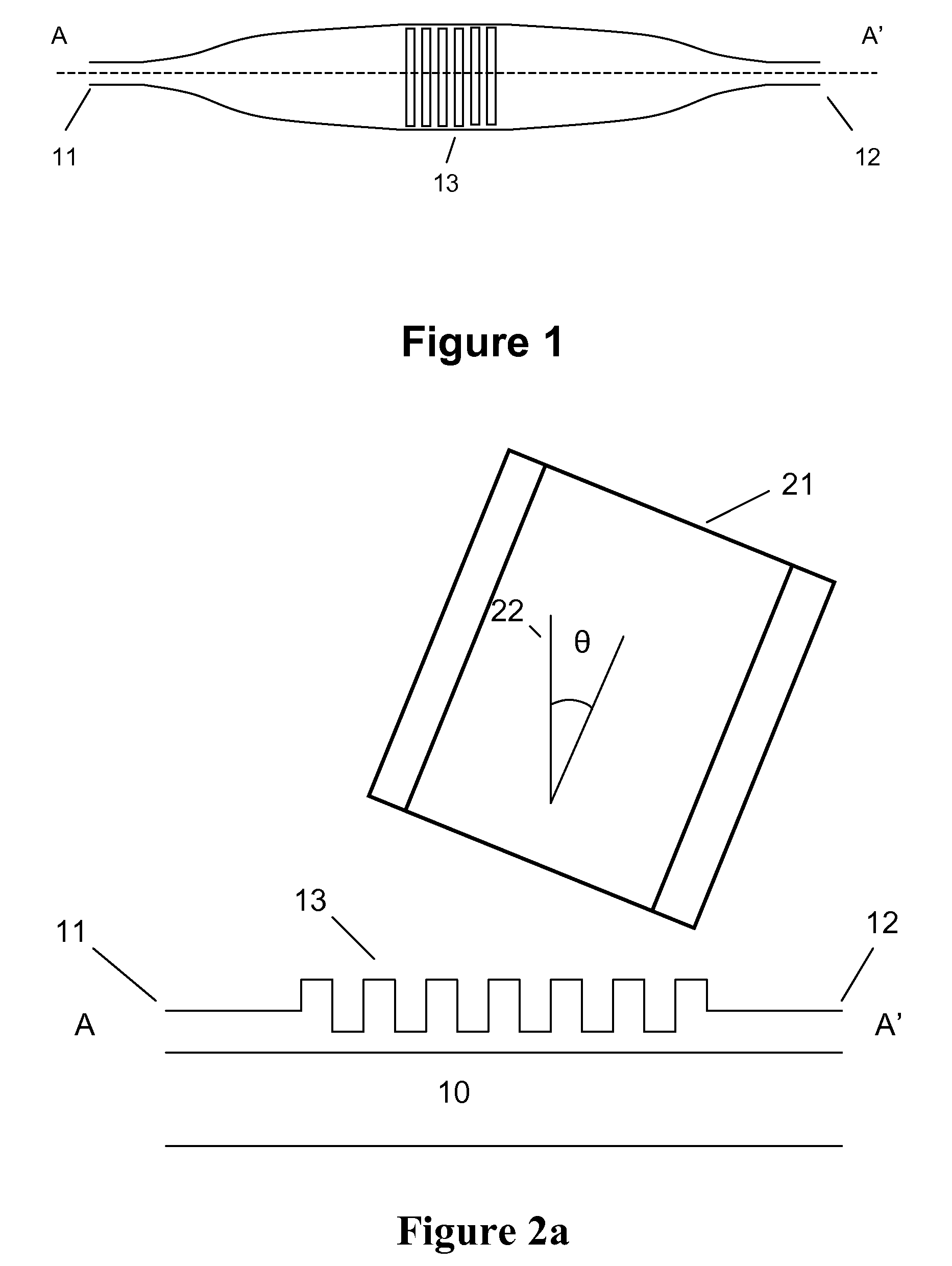
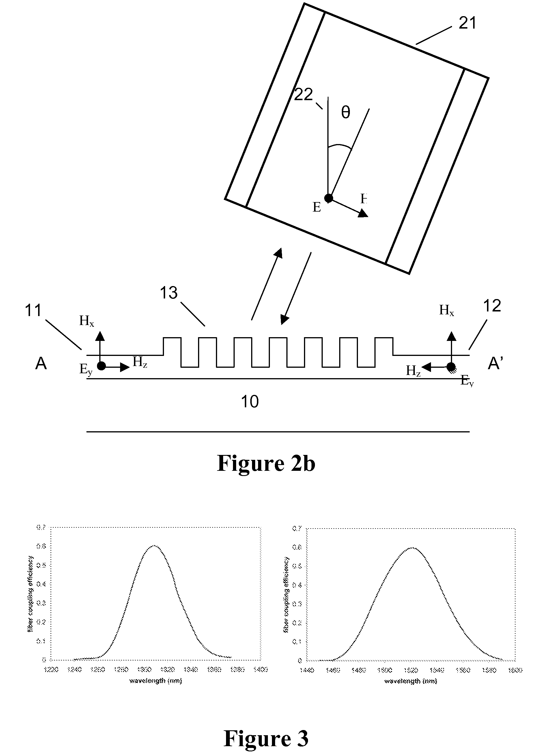
[0063]In a first embodiment, shown in FIGS. 1, 2a and 2b, the optical device in accordance with the present invention comprises a first dielectric waveguide 11 and a second dielectric waveguide 12 on a substrate 10, for example intersecting under a substantially straight angle, and a diffraction grating structure 13 at the intersection of both dielectric waveguides, such as for example a one-dimensional diffraction grating structure. Due to the dispersive properties of the grating structure, there exists a first wavelength or wavelength band for which radiation of that first wavelength traveling within the first dielectric waveguide 11 and exciting the grating structure is diffracted at an angle corresponding to an coupling direction and there exists a second wavelength or wavelength band, different from the first wavelength or wavelength band, for which radiation of that second wavelength traveling within the second dielectric waveguide 12 and exciting the grating structure is diff...
second embodiment
[0073]In a second embodiment according to the present invention, the polarization issue is tackled by using a two-dimensional diffraction grating structure as a coupler and multiplexer. FIG. 6 shows the layout of this embodiment, comprising 4 dielectric optical waveguides 41, 42, 43, 44 which intersect and which form a substantially right angle at the intersection. At the intersection of the 4 waveguides, a two-dimensional grating structure 45 is provided. The latter may be formed in any suitable way, for example by etching an array of holes or rods in the waveguide layer or in the waveguide cladding layer at the intersection or by defining e.g. a dielectric or metallic structured layer on top of the waveguide structure. Although FIG. 6 shows a periodic arrangement of holes, which define the two-dimensional grating structures, also non-periodic structures with composing elements other than holes may be used, i.e. the spacing, size and shape of the features composing the diffraction ...
third embodiment
[0076]In a third embodiment according to the present invention, the polarization issue is tackled for a single wavelength or wavelength band by using a two-dimensional grating structure as a duplexer. An exemplary layout of this embodiment is shown in FIG. 7, comprising three optical dielectric waveguides 51, 52, 53, two of which (51, 52) form a substantially right angle, while the third dielectric waveguide 53 lies along the bisection line CC′ of the two former dielectric waveguides 51, 52. At the intersection of the dielectric waveguides, a two-dimensional grating structure 55 is formed, for example by etching an array of holes or rods in the waveguide layer or in the waveguide cladding layer or by defining e.g. a dielectric or metallic structured layer on top of the waveguide structure. Although FIG. 7 shows a periodic arrangement of holes, which define the two-dimensional grating structures, also non-periodic structures with composing elements other than holes may be used, i.e. ...
PUM
 Abstract
Description
Claims
Application Information
 - R&D
- Intellectual Property
- Life Sciences
- Materials
- Tech Scout
- Unparalleled Data Quality
- Higher Quality Content
- 60% Fewer Hallucinations
Browse by: Latest US Patents, China's latest patents, Technical Efficacy Thesaurus, Application Domain, Technology Topic, Popular Technical Reports.
© 2025 PatSnap. All rights reserved.Legal|Privacy policy|Modern Slavery Act Transparency Statement|Sitemap|About US| Contact US: help@patsnap.com


