Switching device having a non-linear element

a non-linear element and switching device technology, applied in the direction of electrical programme control, program control, instruments, etc., can solve the problems of increased power dissipation, non-scaling of sub-threshold slopes, and preventing proper device operation, so as to achieve high switching speed and low leakage current characteristics , the effect of high density

Active Publication Date: 2014-07-01
CROSSBAR INC
View PDF19 Cites 22 Cited by
  • Summary
  • Abstract
  • Description
  • Claims
  • Application Information

AI Technical Summary

Benefits of technology

[0012]The present invention has a number of advantages over conventional techniques. For example, embodiments of the present invention allow for a high density non-volatile memory characterized by high switching speed, low leakage current characteristic, and high device yield. Depending on the embodiment, one or more of these may be achieved. These and other advantages will be described below in more detail in the present specification.

Problems solved by technology

However, as field effect transistors (FET) approach sizes less than 100 nm, problems such as short channel effect start to prevent proper device operation.
Moreover, such sub 100 nm device size can lead to sub-threshold slope non-scaling and increased power dissipation.
These devices often require new materials and device structures to couple with silicon based devices to form a memory cell, which lack one or more key attributes.
For example, Fe-RAM and MRAM devices have fast switching characteristics and good programming endurance, but their fabrication is not CMOS compatible and size is usually large.
Switching for a PCRAM device uses Joules heating, which inherently has high power consumption.
Organic RAM or ORAM is incompatible with large volume silicon based fabrication and device reliability is usually poor.
As a result, dark current or leakage current becomes more of a problem, where leakage current can return a false result for a read operation or cause an unintentional state change in a cell.
The problem of leakage current is particularly acute in two-terminal devices, in which multiple memory cells can form leakage paths through interconnecting top and bottom electrodes.
However, the external diode approach has several disadvantages.
Because most diodes rely on a P / N junction, it is difficult to scale the diode height to achieve a memory and diode structure with a desirable aspect ratio.
And finally, a conventional diode is only compatible with a unipolar switching device, and not a two-way bipolar device.

Method used


Image

  • Switching device having a non-linear element
  • Switching device having a non-linear element
  • Switching device having a non-linear element

Examples


Embodiment Construction

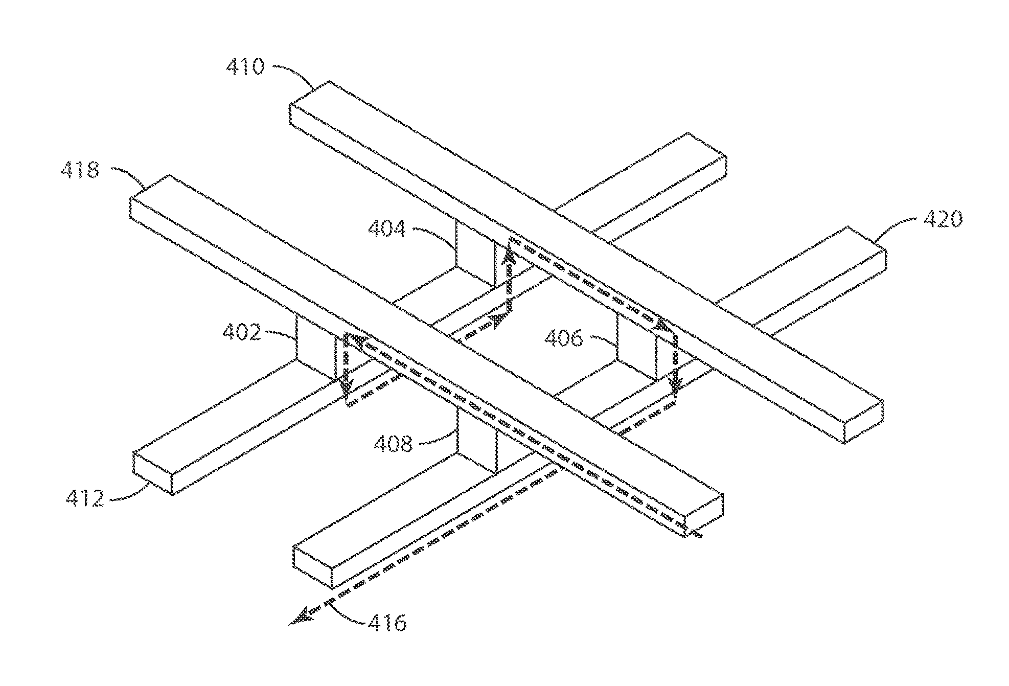
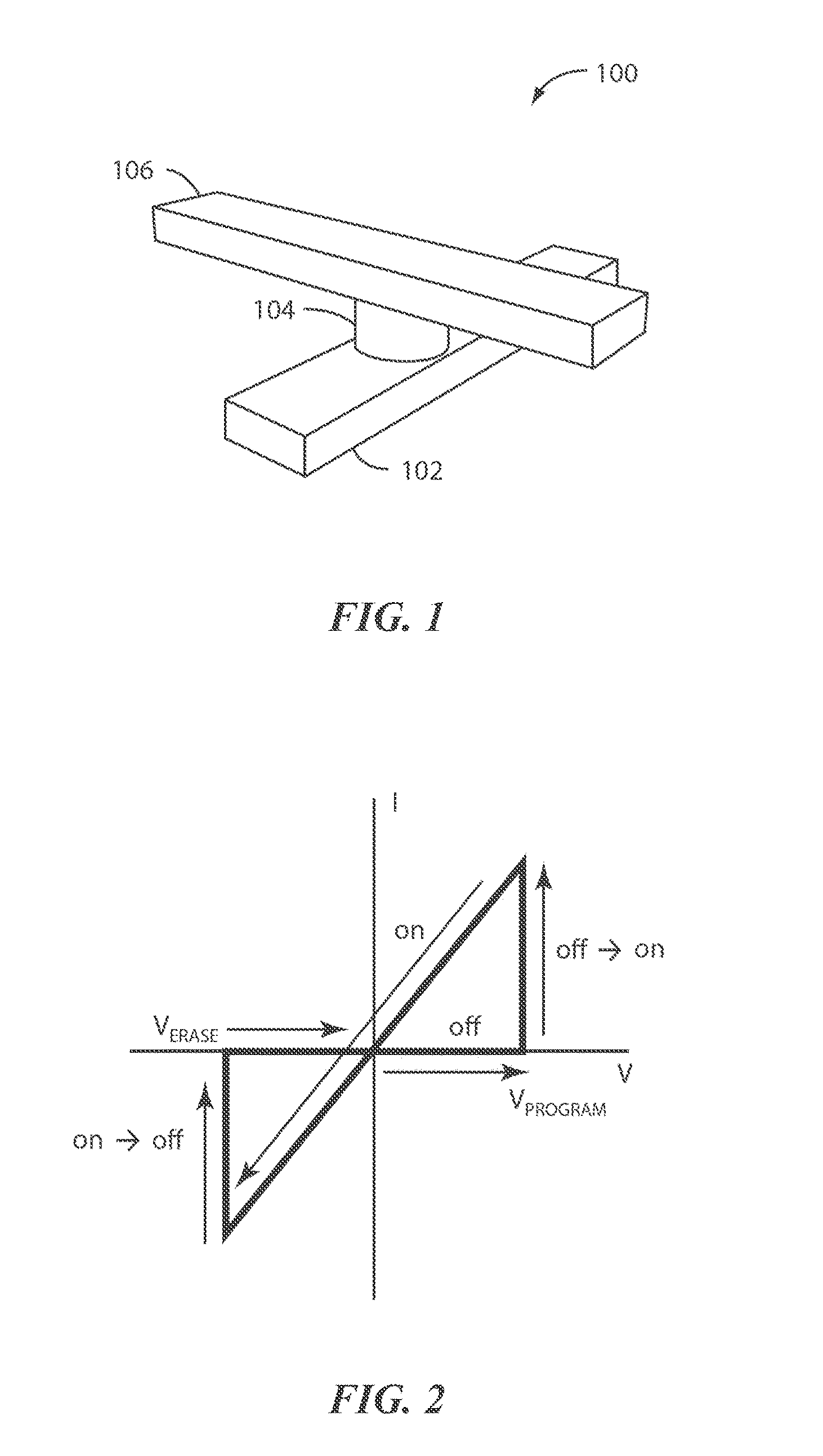
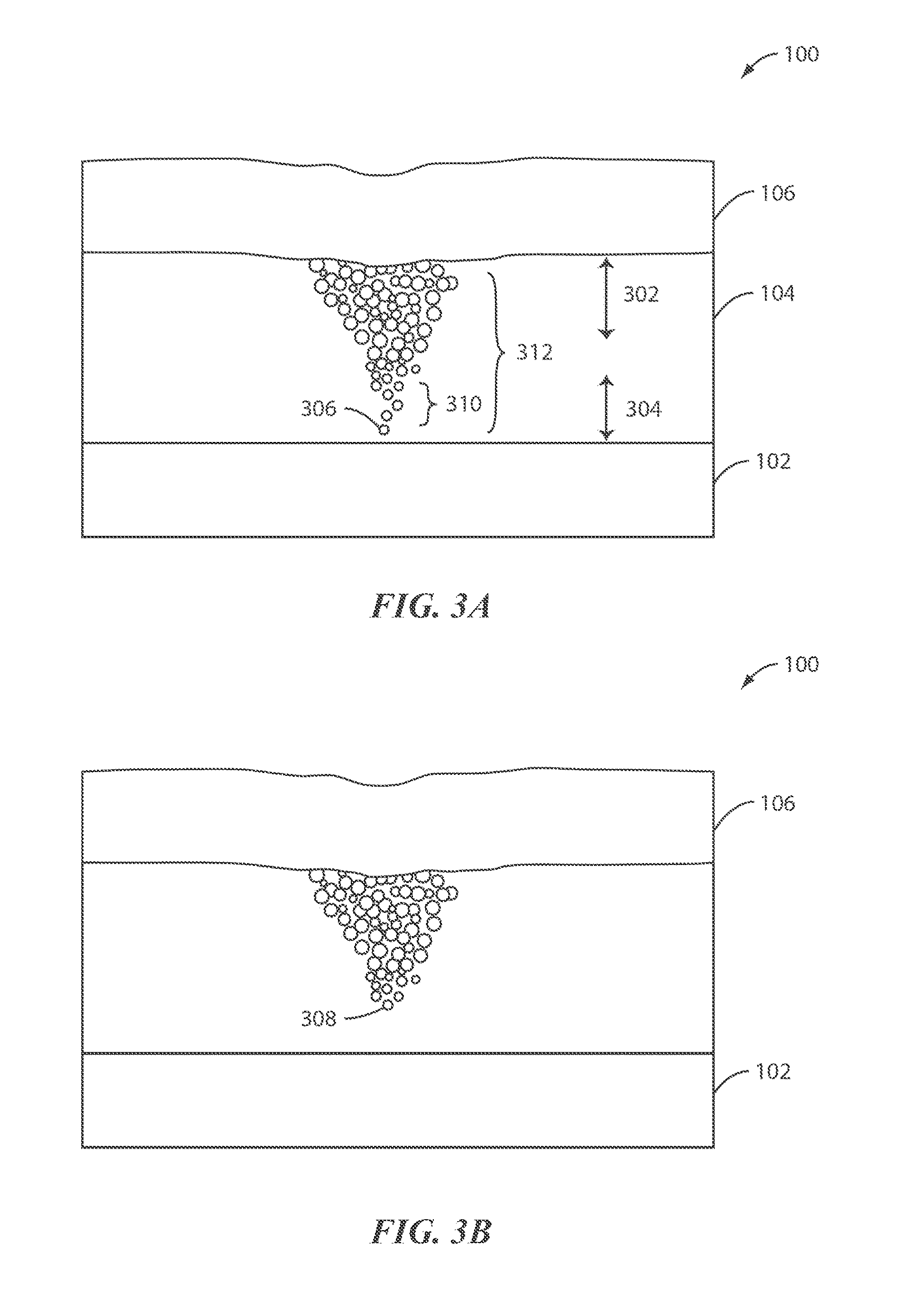
[0032]The present invention is generally directed to a memory device. More particularly, the present invention provides a structure and a method for a resistive switching cell having a nonlinear element. The switching cell may be used in a Resistive Random Access Memory (RRAM) or any highly integrated device. It should be recognized that embodiments of the present invention can have a broader range of applicability. Although the present invention is described with respect to specific embodiments, the embodiments are only used for illustrative purposes and should not be considered limiting.

[0033]RRAM is typically a two terminal device in which a switching element is sandwiched between a top electrode and a bottom electrode. The resistance of the switching element is varied by applying a voltage to the electrodes or a current through the switching element. Resistive switching can be bipolar or unipolar. In bipolar switching, the change in resistance of the switching element depends on...


PUM


Abstract

Method for a memory including a first, second, third and fourth cells include applying a read, program, or erase voltage, the first and second cells coupled to a first top interconnect, the third and fourth cells coupled to a second top interconnect, the first and third cells coupled to a first bottom interconnect, the second and fourth cells are to a second bottom interconnect, each cell includes a switching material overlying a non-linear element (NLE), the resistive switching material is associated with a first conductive threshold voltage, the NLE is associated with a lower, second conductive threshold voltage, comprising applying the read voltage between the first top and the first bottom electrode to switch the NLE of the first cell to conductive, while the NLEs of the second, third, and the fourth cells remain non-conductive, and detecting a read current across the first cell in response to the read voltage.

Description

CROSS REFERENCE TO RELATED APPLICATIONS[0001]This application claims priority to and is a continuation-in-part of U.S. application Ser. No. 13 / 149,757, filed May 31, 2012. This application also claims priority to U.S. application Ser. No. 13 / 290,024, filed Nov. 4, 2011, which is a non-provisional of U.S. Application No. 61 / 410,035, filed Nov. 4, 2010, U.S. Application No. 61 / 712,171, filed Oct. 10, 2012, and U.S. application No. 61 / 786,100, filed Mar. 15, 2013. These cited documents are incorporated by reference herein, for all purposes.JOINT RESEARCH AGREEMENT[0002]The presently claimed invention was made by or on behalf of the below listed parties to a joint university-corporation research agreement. The joint research agreement was in effect on or before the date the claimed invention was made and the claimed invention was made as a result of activities undertaken within the scope of the joint research agreement. The parties to the joint research agreement are The University of M...

Claims


Application Information

Patent Timeline
Patent Type & Authority Patents(United States)
IPC IPC(8): G11C11/00H01L45/00
CPCG11C13/004G11C13/0004G11C13/0007G11C13/003G11C13/0069G11C13/0097G11C2213/15G11C2213/56G11C2213/77H01L27/101H01L27/2409H01L27/2463H01L45/085H01L45/1233H01L45/145H01L45/148G11C2213/76G11C2213/73H10B63/20H10B63/80H10N70/245H10N70/826H10N70/883H10N70/884
Inventor LU, WEIJO, SUNG HYUNNAZARIAN, HAGOP
Owner CROSSBAR INC
Why Eureka
Try Eureka