
All-solid-state reflective dimming electrochromic element sealed with protective layer, and dimming member comprising the same

a technology of electrochromic elements and dimming elements, which is applied in the direction of door/window protective devices, coatings, instruments, etc., can solve the problems of difficult application of this element to an increased area, difficult to reduce trim temperature, and high interior temperature of automobiles in a certain environment, etc., to achieve excellent reflective dimming properties, easy to use, and easy to use

Inactive Publication Date: 2014-07-08
NAT INST OF ADVANCED IND SCI & TECH
View PDF8 Cites 9 Cited by
  • Summary
  • Abstract
  • Description
  • Claims
  • Application Information

AI Technical Summary

Benefits of technology

The patent describes an all-solid-state reflective dimming electrochromic element that has excellent reflective dimming properties and can be produced in large size. The element consists of a multilayer film formed on a transparent substrate, including a transparent conductive film layer, an ion storage layer, a solid electrolyte layer, a buffer layer, a catalyst layer, a reflective dimming layer, and a protective layer. The element can be switched between a mirror state and a transmission state by applying a voltage or flowing a current, allowing for the electrical control of sunlight transmission. The protective layer improves durability to environment. The invention also provides a method for producing the element using a high-speed process at a low cost. Additionally, the invention provides a method for easily incorporating a dimming member into existing window glass or the like to achieve energy saving.

Problems solved by technology

Particularly, in an automobile, the ratio of the window glass to the space is larger than that in a building structure, and further an automobile hardly avoids exposure to sunlight, and hence the temperature of the interior of the automobile in a certain environment, e.g., under the blazing sun is likely to become extremely high.
An example of measurement made in an environment of summer in Japan shows that the temperature in a parked automobile is close to 70° C. With respect to the temperature of the trim of the interior of the automobile, the temperature of the upper surface of an instrument panel is increased to about 100° C., and the temperature of a ceiling is increased to about 70° C. Further, even when using a ventilating or cooling apparatus, the trim is not easily lowered in temperature and continues radiating heat toward a driver and a passenger(s) for a long time to make them feel uncomfortable.
For this reason, when the dimming material having such a dimming principle is employed, there is a problem in that the dimming material has heat due to the absorption of the light, so that the heat of the dimming material is re-radiated to the interior as radiation heat.
This element, however, uses an expensive rare earth metal in the reflective dimming layer, and therefore, from the viewpoint of the cost, the application of this element to an increased area is difficult.
However, the material of this type in the transparent state has such a low transmittance that the material cannot be practically used.
The all-solid-state dimming mirror light switch using a magnesium-nickel alloy thin film has a problem in that the switch in the transmission state is colored pale yellow and is not in a completely colorless and transparent state.
However, with respect to the repeated use, this element has a disadvantage in that the element can achieve switching 1,000 times or more, but the resultant element suffers deterioration and thus cannot revert to the reflection state.
As a result, the surface magnesium oxide layer had a so poor function as a passive layer that rapid deterioration of the layer was observed in a high humidity atmosphere.

Method used


Image

  • All-solid-state reflective dimming electrochromic element sealed with protective layer, and dimming member comprising the same
  • All-solid-state reflective dimming electrochromic element sealed with protective layer, and dimming member comprising the same
  • All-solid-state reflective dimming electrochromic element sealed with protective layer, and dimming member comprising the same

Examples


example 1

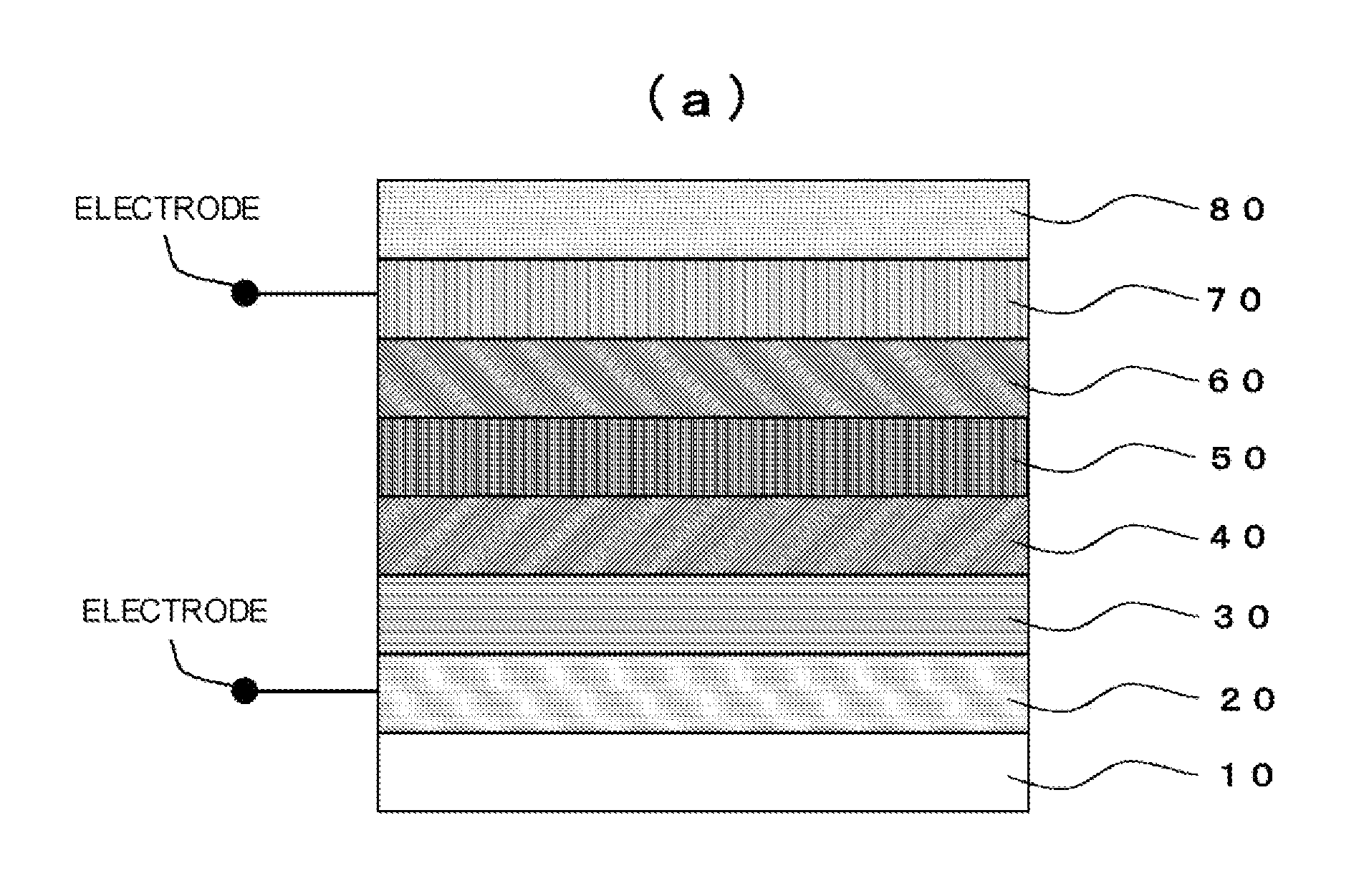
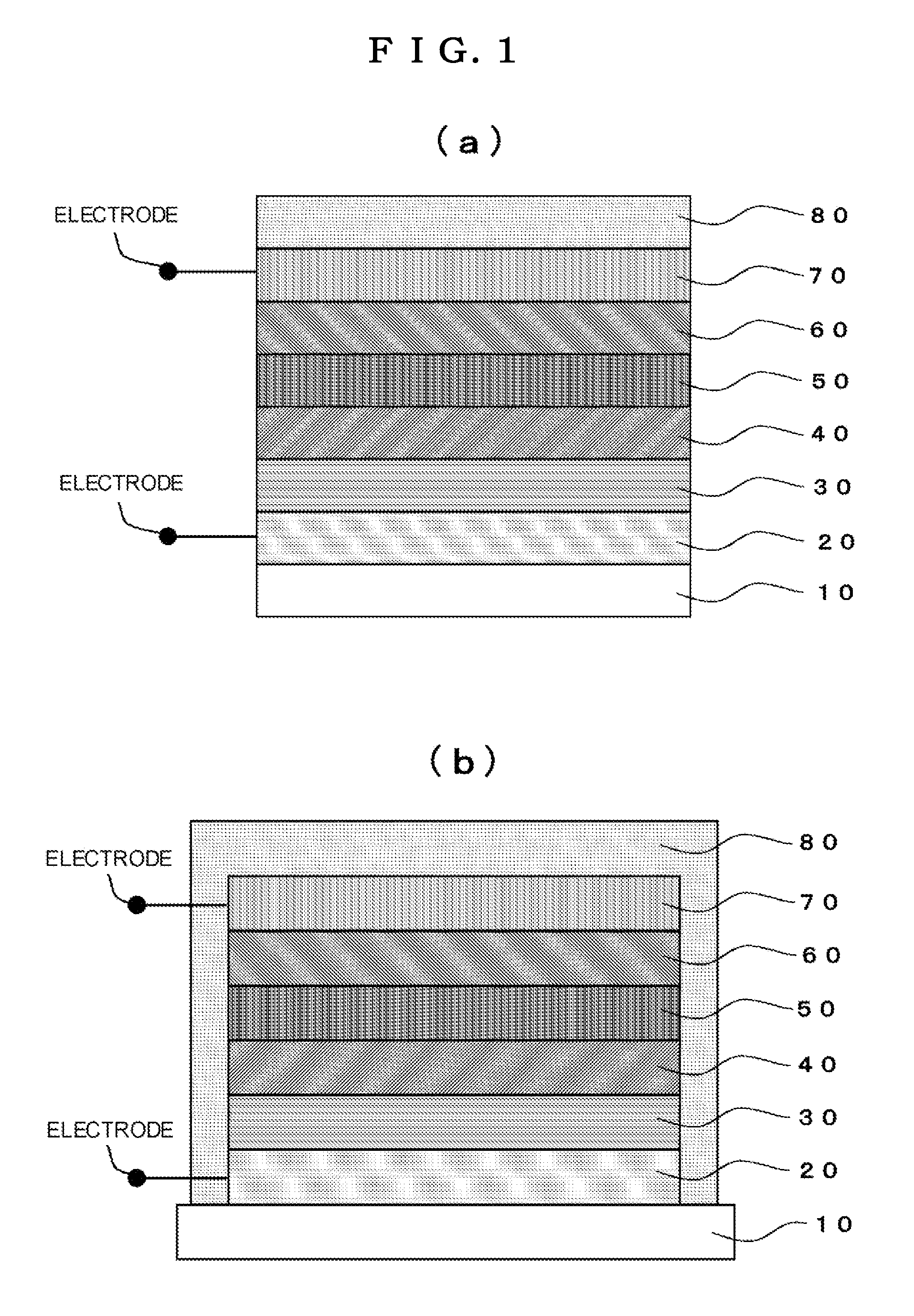
[0129]Example 1 of the invention is described below. In Example 1, an electrochromic element having the construction shown in FIGS. 1(a) and 1(b) was prepared.

[Preparation of an Electrochromic Element]

[0130]A transparent substrate of a glass sheet having a thickness of 1.1 mm was coated with a tin-doped indium oxide having a surface resistance of 10Ω / □ as a transparent conductive film layer. The resultant substrate was set in a vacuum apparatus, and the apparatus was evaluated to create a vacuum.

[0131]Then, on the transparent conductive film layer, a tungsten oxide thin film was deposited as an ion storage layer by a reactive direct current (DC) magnetron sputtering method using a magnetron sputtering machine. In the deposition of film, sputtering was performed by applying a power of 80 W to a metallic tungsten target in a mixed gas atmosphere having an argon gas to oxygen gas flow rate ratio controlled to 7:1.5 at a pressure of 1.0 Pa in the vacuum chamber. The deposited tungsten o...

example 2

Preparation of an Electrochromic Element

[0149]Tungsten oxide, tantalum oxide, aluminum, palladium, and magnesium-nickel alloy thin films were deposited on a glass substrate having a transparent conductive film using a magnetron sputtering method in accordance with the same procedure as in Example 1. The conditions for the depositions of respective films are the same as those in Example 1.

[0150]A solution of a mixture of a polyvinyl chloride and tetrahydrofuran was applied as a protective layer by a spin coating method so that the resultant protective layer sealed the multilayer film including the magnesium-nickel alloy thin film as a reflective dimming layer. As the coating solution, a solution obtained by dissolving 1 g of a polyvinyl chloride in 50 ml of tetrahydrofuran was used. After the application, the resultant element was kept in a thermostat at 50° C. so that the solvent was allowed to volatilize to form a protective layer of the polyvinyl chloride, preparing an electrochro...

example 3

Preparation of an Electrochromic Element

[0159]Tungsten oxide, tantalum oxide, aluminum, palladium, and magnesium-nickel alloy thin films were deposited on a glass substrate having a transparent conductive film using a magnetron sputtering method in accordance with the same procedure as in Example 1. The conditions for the depositions of respective films are the same as those in Example 1.

[0160]A fluororesin (DURASURF DS-5400, manufactured by Harves Co., Ltd.) was applied as a protective layer by a spin coating method so that the resultant protective layer sealed the multilayer film including the magnesium-nickel alloy thin film as a reflective dimming layer. After the application, the solvent component was allowed to spontaneously volatilize to form a protective layer of the fluororesin on the surface of element, preparing an electrochromic element.

[Change with Time of the Optical Transmittance and Optical Reflectance]

[0161]The obtained element was set in the evaluation apparatus sh...


PUM

PropertyMeasurementUnit
total transmittanceaaaaaaaaaa
water absorptionaaaaaaaaaa
cure shrinkageaaaaaaaaaa

Abstract

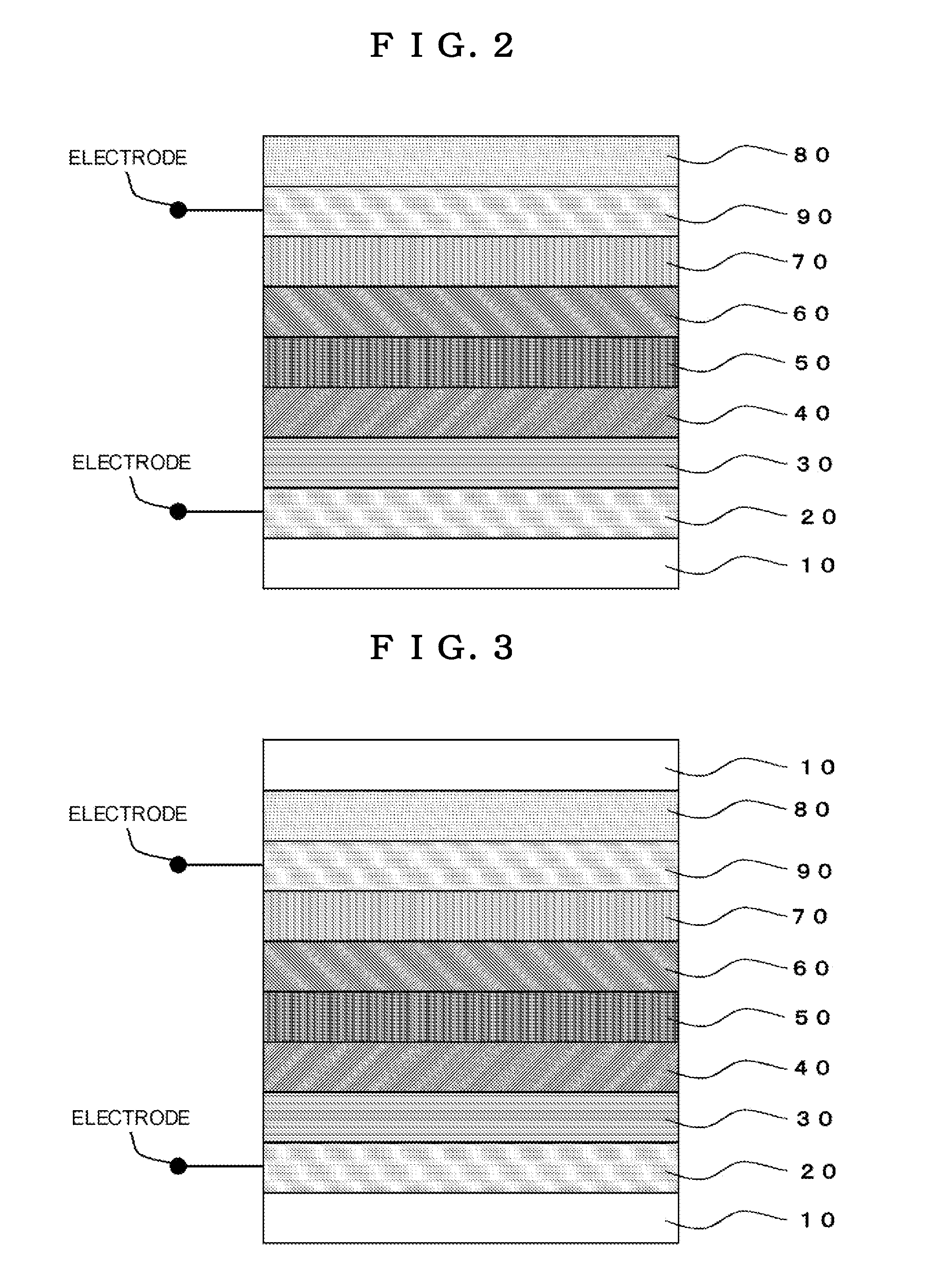
An all-solid-state reflective dimming electrochromic element having a multilayer film formed on a transparent substrate, which is characterized in that the multilayer film has a multilayer structure comprising at least a transparent conductive film layer, an ion storage layer, a solid electrolyte layer, a buffer layer, a catalyst layer, a reflective dimming layer, and a protective layer formed on the transparent substrate, and which is sealed with the protective layer, and a dimming member comprising the same are provided.

Description

TECHNICAL FIELD[0001]The present invention relates to an all-solid-state reflective dimming electrochromic element sealed with a protective layer and a dimming member comprising the same, and more particularly to an all-solid-state reflective dimming electrochromic element which can be electrically controlled in the transmission of light or heat by electrically and reversibly switching the surface of glass from the mirror state to the transmission state, and a dimming member comprising the same.BACKGROUND ART[0002]Generally, the window glass for a building serves as a large outlet or inlet of heat, and, for example, when the inside of a building is heated in winter, about 48% of the heat of the inside is taken away from the window, and, when the inside of a building is cooled in summer, about 71% of the heat of the inside comes from the outside through the window. A similar phenomenon occurs in vehicles for movement and the like. Particularly, in an automobile, the ratio of the wind...

Claims


Application Information

Patent Timeline
Patent Type & Authority Patents(United States)
IPC IPC(8): G02F1/153
CPCC03C17/36C03C17/3618C03C17/3639C03C17/3649C03C17/3655C03C17/3657C03C17/3681C03C2217/948C03C2218/154E06B9/24E06B2009/2464G02F1/153G02F2001/1536G02F2203/02
Inventor TAJIMA, KAZUKIYAMADA, YASUSEIYOSHIMURA, KAZUKI
Owner NAT INST OF ADVANCED IND SCI & TECH
Learn More