Devices, apparatus, and methods employing biomimetic cilia for microfluidic manipulation

a technology of microfluidic manipulation and cilia, which is applied in the direction of positive displacement liquid engines, machines/engines, laboratory glassware, etc., can solve the problems of inability to achieve micro/nanoscale fluid manipulation using cilia actuation, and achieve the effect of reducing errors, minimizing non-specific binding of dna probes/targets, and evaluating the biomixing performance of cilia devices

Inactive Publication Date: 2014-07-15
UNIV OF WASHINGTON
View PDF5 Cites 10 Cited by
  • Summary
  • Abstract
  • Description
  • Claims
  • Application Information

AI Technical Summary

Benefits of technology

[0159]The goal of this task is to evaluate the biomixing performance of the cilia devices by using a DNA hybridization assay. Compared with the avidin-biotin assay in our preliminary result, the binding constant of DNA hybridization is 106 M. Thus, the effect of the mixing can be shown dramatically because the success of single hybridization events depends upon the probability of a thermodynamic reversible process of DNA-DNA intermolecular collision.
[0160]The mixing efficiency of the assay is evaluated in terms of the assay time, the sensitivity, and the specificity. In this experiment, the effect of cilia-induced mixing is compared with the diffusion-controlled effect. The detections of DNA hybridi...

Problems solved by technology

While there is significant interest in fluid manipulation using cilia-based mechanisms, micro/nanoscale fluid manipulation using cil...

Method used


Image

  • Devices, apparatus, and methods employing biomimetic cilia for microfluidic manipulation
  • Devices, apparatus, and methods employing biomimetic cilia for microfluidic manipulation
  • Devices, apparatus, and methods employing biomimetic cilia for microfluidic manipulation

Examples


example one

Biomimetic Silicone Cilia for Microfluid Manipulation

I. Experimental Configuration

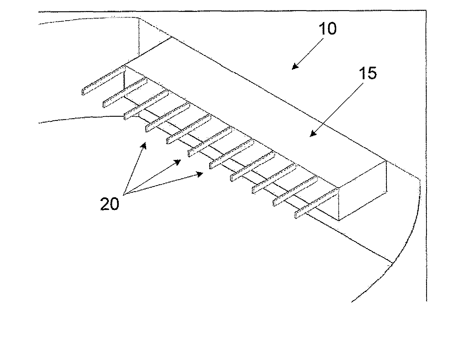
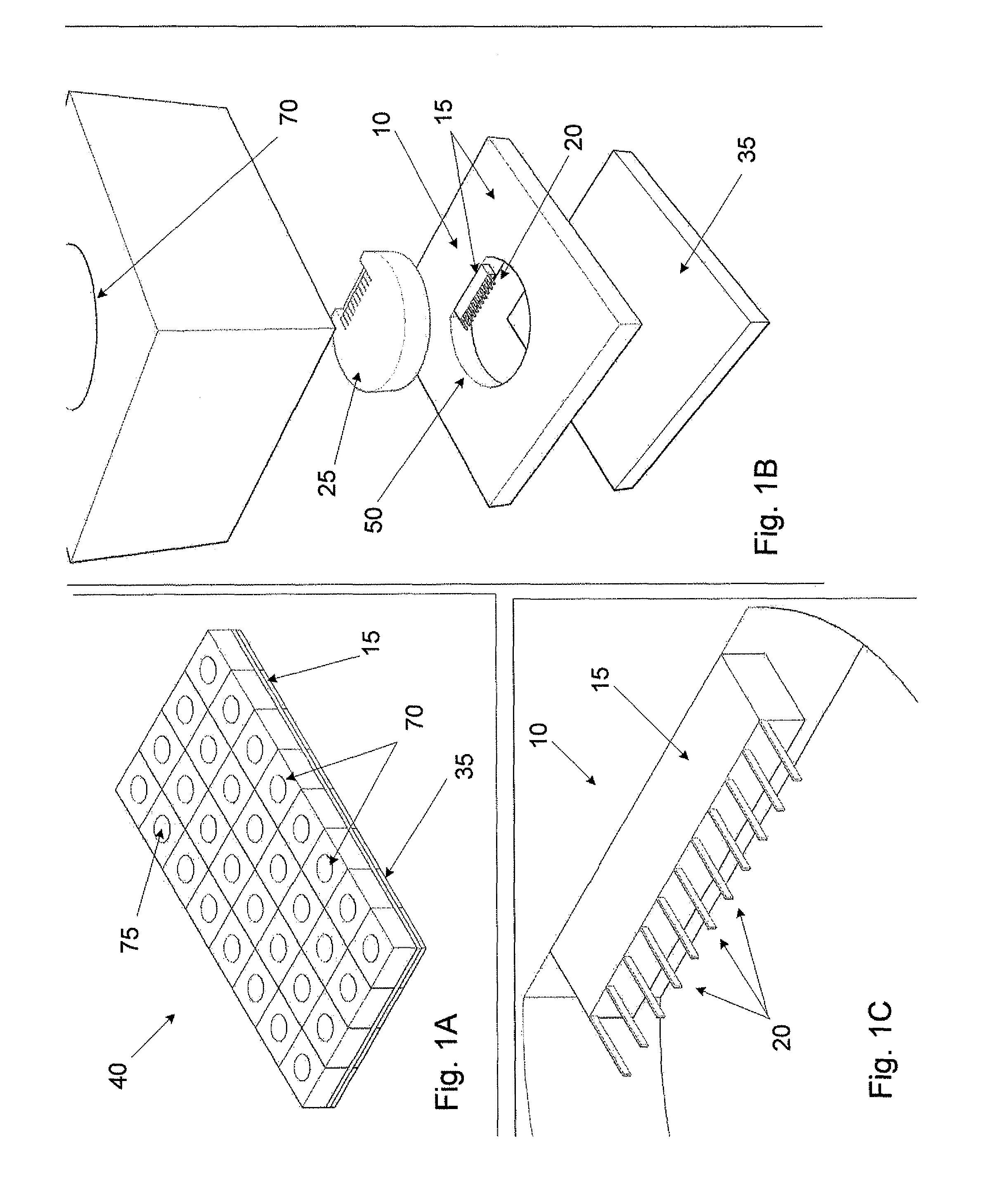
[0108]To demonstrate the underwater fabrication process, a device was fabricated as shown in FIGS. 10A-C. The device was composed of a 1 mm-thick glass slide, a chamber, a supporting block, a cilia structure, and a cover plate as shown in FIGS. 10A-C. The fluidic chamber was made of a cured 2 mm-thick PDMS plate. The PDMS plate had a 27 mm×7 mm (W×D) rectangular window in the center. A 25 mm×5 mm×0.7 mm (W×D×H) PDMS block was prepared to support a cilia structure. The device was covered with a 0.4 mm PDMS plate. A cilia array was assembled in a fluidic device with the underwater fabrication process, described below.

[0109]FIG. 11 shows the schematics of the experimental set-up to excite the cilia, measure the cilia response, and also trace the microfluid motion. For the excitation of the cilia device, a leadzirconate-titanate (PZT) microstage (PZS-200, Burleigh Instruments, Inc.) was controlled by a sig...

example two

Fluid Manipulation by Biomimetic Cilia

I. Fabrication

[0130]1. Fabrication of the PDMS Cilia Structure

[0131]Two kinds of cilia array were fabricated for fluid actuation; both vertical and horizontal cilia array were fabricated according to the methods used in “Example One” above. Deep reactive ion etching (DRIE) with the standard Bosch process (ICP 380, Oxford Instruments) was used to fabricate a high aspect ratio the structure. To remove the Bosch polymers generated in DRIE, the wafer was etched by O2 plasma at 300 W power for 10 minutes (Model 2000, Branson), followed by removing the photoresist in H2O2+H2SO4 mixture (1:3) for 10 minutes. The processed wafer was rinsed in flowing de-ionized (DI) water for 15 minutes. After drying the Si mold by nitrogen gas flow, it was silanized with tridecafluoro-1,1,2,2-tetrahydroctyl-1-trichlorosilane (United Chemical Technolgies, Inc.) for 2 hours in a desiccator in order to grow the monolayer. It helped release a cured PDMS structure from the ...

example three

Cilia Device for Microfluid Manipulation

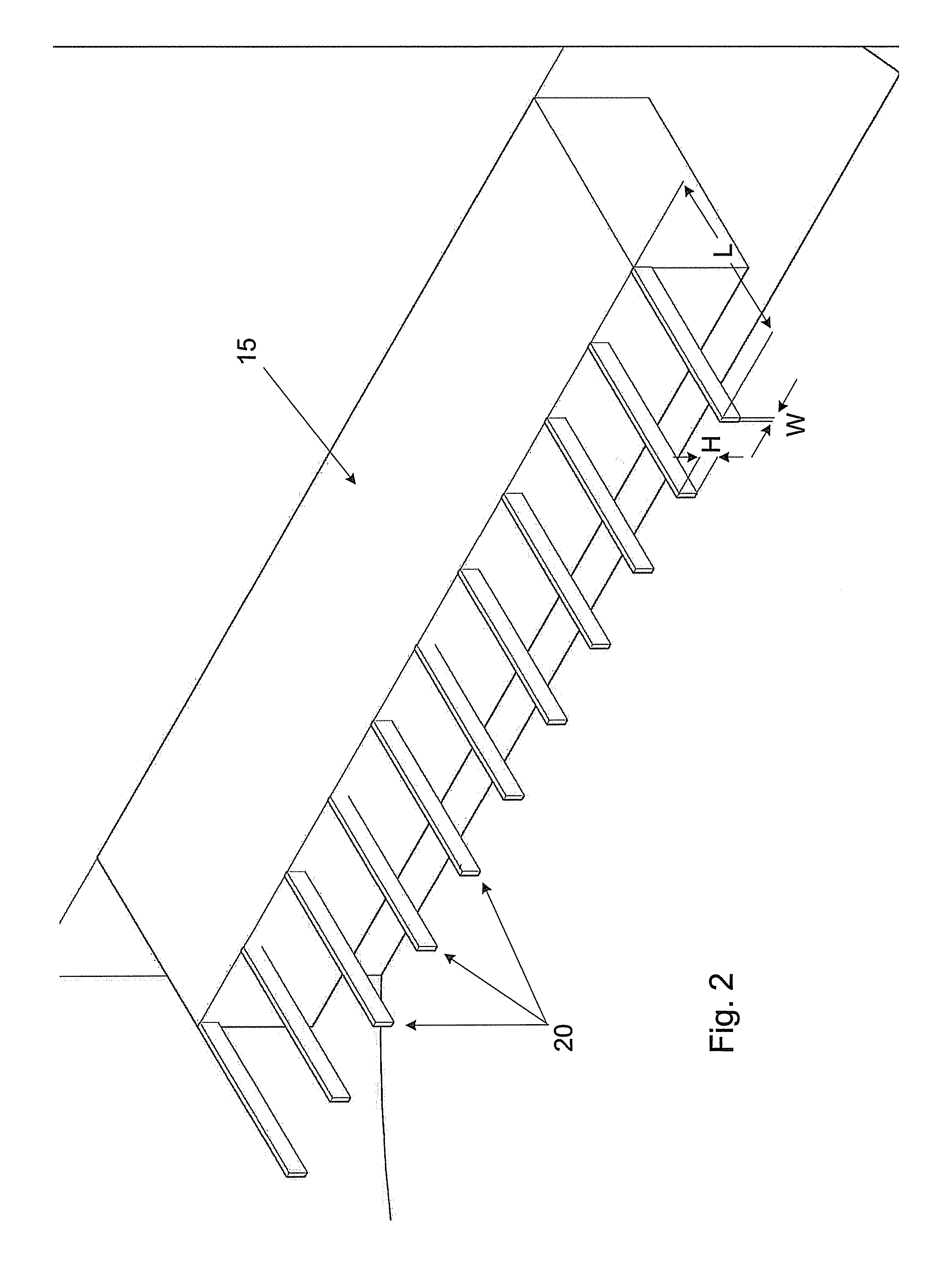
[0145]A cilia device for resonating the cilia in water was fabricated in accordance with the manufacturing methods discussed above to achieve cilia with a 10 μm width, 75 μm height, and 420 μm length with the cilia spaced apart by 200 μm. A fluoreporter biotin quantitation assay kit (Invitrogen, Carlsbad, Calif.) was used to determine the reaction performance. The mixing performance of the cilia device was evaluated by three kinds of experiments; (1) diffusion, (2) vibration without cilia and (3) cilia actuation.

[0146]The zig-zag and rotational motion of the microspheres was observed in the cilia device. This complex flow could enhance bioreaction by increasing a molecular collision rate. According to the avidin-biotin experiments, the detection sensitivity due to the cilia-actuation was enhanced by 1000 times those of the other cases, as shown in FIG. 19. Considering the versatile fabrication and actuation protocols, the proposed cilia can be...


PUM


Abstract

A device comprises: one or more cantilevered biomimetic cilia, and a liquid disposed among the one or more biomimetic cilia, wherein individual biomimetic cilia are at least partially submerged in the liquid, and wherein the biomimetic cilia are arranged for excitation into resonance, such as for mixing and pumping via the resonant behavior of the excited cilia.

Description

PRIORITY CLAIM[0001]This application claims priority to Provisional Application Ser. No. 61 / 108,801 filed Oct. 27, 2008 the disclosure of which is expressly incorporated herein by reference.GOVERNMENT RIGHTS[0002]The United States government may have certain rights in this invention pursuant to Government Grant #CMMI0624597 with the National Science Foundation.BACKGROUND OF THE INVENTION[0003]Fluid manipulation at the microscale is very important for biomolecule mixing and drug delivery. In nature, the rhythmic beating of biological cilia can provide motility for cells and microorganisms. For example, the movement of cilia transports fluids and particles in biological ducts. The motion of biological cilia can be an effective and safe method for biomolecule handling, especially in a microscale environment where the Reynolds number is low. To date, various approaches have attempted to mimic naturally-occurring, biological cilia, none of which have proved satisfactory.FIGURES[0004]FIG....

Claims


Application Information

Patent Timeline
IPC IPC(8): B01L3/00B01F13/00
CPCB01F13/0059F04B19/00B01L2300/0816B01L2400/0433B01L3/50273B01L2400/0415B01L2300/0829B01F13/0091B01L2400/043B01L2400/0484B01L3/502707B01L3/5085B01F13/0064B01L3/502746B01L3/502761F04B43/0054F04B43/0009B01F33/3038B01F33/30B01F33/3017
Inventor CHUNG, JAEDEVASIA, SANTOSHRILEY, JAMES J.OH, KIESEOKLEE, KYONG HOONKONGTHON, JIRADECH
Owner UNIV OF WASHINGTON
Why Eureka
Try Eureka