Methods and systems for coherent imaging and feedback control for modification of materials

a technology of coherent imaging and feedback control, applied in auxillary shaping apparatus, spectrometry/spectrophotometry/monochromator, optical radiation measurement, etc., can solve the problems of affecting the standard technique, affecting the safety and efficiency of use of current mechanical tools, and affecting the axial direction of the laser's action

Active Publication Date: 2014-09-02
LASER DEPTH DYNAMICS INC +1
View PDF16 Cites 62 Cited by
  • Summary
  • Abstract
  • Description
  • Claims
  • Application Information

AI Technical Summary

Problems solved by technology

However, localizing the laser's action in the axial direction of the beam can be difficult.
Aspects of the laser interaction and practical limitations can interfere with the standard techniques.
Some examples of such aspects include plasma generation / electrical interference, high aspect ratio holes, blinding by the processing laser, fast moving material, unpredictable geometries, material relaxation and potential damage to the metrology instrumentation by the processing laser.
Current mechanical tools are archaic and difficult to use safely and efficiently except by experienced surgeons.
However, lasers have very poor axial control (meaning, the beam continues in the axial direction).
This means that if the point of perforation is not controlled with extreme precision, unintended injury to surrounding soft tissue is almost certain.
Thus, the use of lasers has so far been precluded in a vast number of cases.
However, this assumption is not always a good one and furthermore, one often does not know exactly how much tissue needs to be removed a priori.
Unlike corneal laser surgery, these surgical specialties are mainly concerned with nontransparent, optically turbid tissue types with heterogeneous tissue properties on the microscopic scale, where detailed and precise a priori opto-thermal characterization is not feasible.
The resultant nondeterministic tissue cutting / ablation process greatly hinders the use of lasers during such surgeries.
For example, several authors have recently highlighted that practical laser osteotomy (surgical procedure to cut bone) is limited by a lack of laser depth control.
Although laser ablation of heterogeneous or multi-layered samples has been accomplished, these processes require tremendous amounts of development and rely on uniform sample characteristics or models with limited applicability and varied success.
Laser welding and cleaning, too, typically require extensive multi-parameter optimization.
Accordingly, industrial laser process development requires significant time and financial investment, and may demand fine tolerance feedstock to ensure reliability.
These forms of metrology do not provide an accurate measurement of laser beam penetration depth.
Axial control (depth of the PCR) and subsequent thermal diffusion are problematic in thick materials.
As a result, the light-matter interaction region inside the PCR can be turbulent, unstable and highly stochastic.
Unfortunately, instability of keyhole formation can lead to internal voids and high weld porosity resulting in weld failure, with potential catastrophic consequences.
Weld quality verification is usually required, often using expensive ex situ and destructive testing.
Welding imaging solutions are offered but are limited in their capabilities and usually monitor regions either before or after of the PCR, to track the weld joint, or record the top surface of the cooled weld joint.

Method used


Image

  • Methods and systems for coherent imaging and feedback control for modification of materials
  • Methods and systems for coherent imaging and feedback control for modification of materials
  • Methods and systems for coherent imaging and feedback control for modification of materials

Examples


implementation example showing verification

of Drilling Control

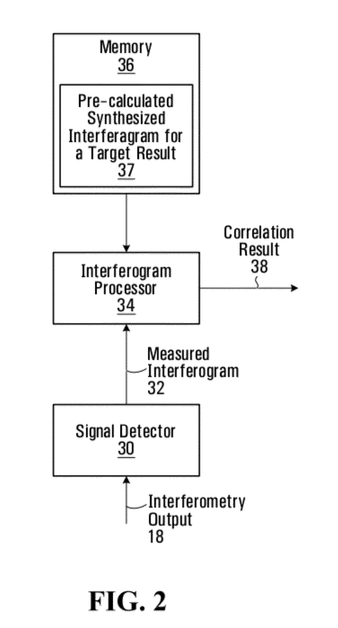
[0412]Using the fully automatic depth control provided by the Inline Coherent Imaging system shown in FIG. 5, 14 holes were drilled at depths that vary steadily by 30 micrometer from hole to hole. The homodyne filter algorithm running on a PC (one embodiment of image processing electronics, 332) was used to efficiently process the raw imaging data from the silicon line camera (330) and make a determination as to whether further machining laser exposure was required to achieve the desired depth. A user programmed the desired depth(s) for the series of holes into the PC. The PC read this programming and synthesized the appropriate homodyne waveforms to mix with the raw imaging data to obtain the sample reflectivity at the target depth. Through the course of drilling the hole, when a selected threshold was met from the homodyne output (in this case, 5 times the RMS intensity of the noise floor), the PC signals the feedback controller (334) to cease the process. In th...


PUM

PropertyMeasurementUnit
depthaaaaaaaaaa
widthaaaaaaaaaa
widthaaaaaaaaaa

Abstract

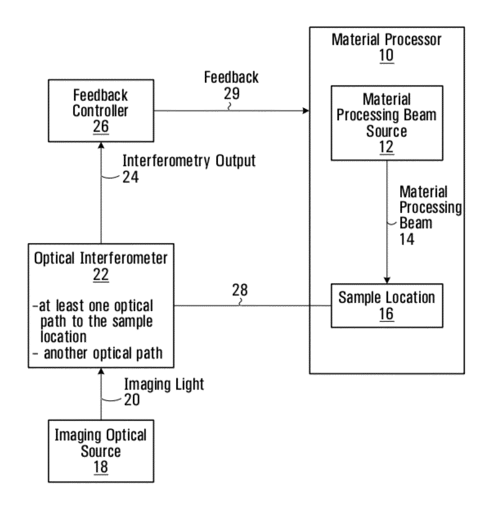
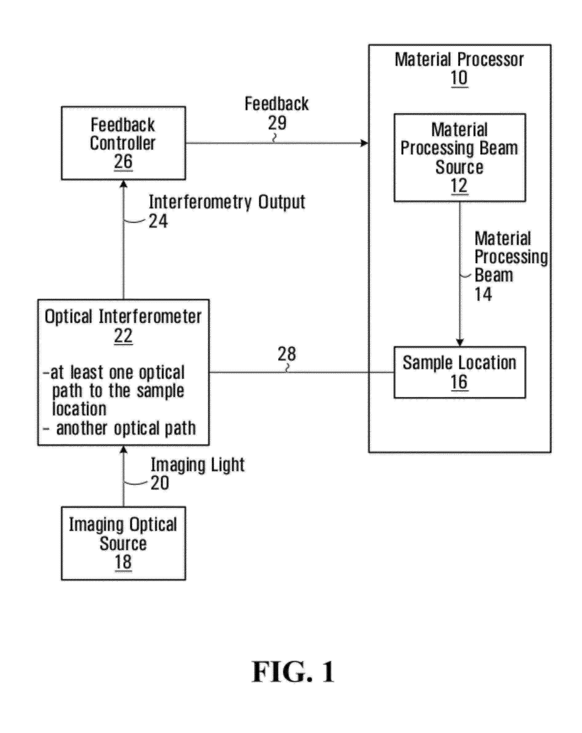
Methods and systems are provided for using optical interferometry in the context of material modification processes such as surgical laser or welding applications. An imaging optical source that produces imaging light. A feedback controller controls at least one processing parameter of the material modification process based on an interferometry output generated using the imaging light. A method of processing interferograms is provided based on homodyne filtering. A method of generating a record of a material modification process using an interferometry output is provided.

Description

RELATED APPLICATIONS[0001]This application claims the benefit of U.S. Provisional Application No. 61 / 386,496 filed Sep. 25, 2010, and U.S. Provisional Application No. 61 / 435,076 filed Jan. 21, 2011, both hereby incorporated by reference in its entirety.FIELD[0002]The application relates to coherent imaging, and to optical modification or measurement of materials, such as through the use of lasers.BACKGROUND OF THE INVENTION[0003]Lasers are known to be important tools for processing a wide range of materials. Example processes include welding, drilling, cutting, routing, perforating, sintering and surface treatment. Materials can include metals, semiconductors, dielectrics, polymers, as well as hard and soft biological tissue. By focusing a beam, it can be possible to achieve improved precision of the laser's action in a direction transverse to the beam axis. However, localizing the laser's action in the axial direction of the beam can be difficult.[0004]Common to many laser processe...

Claims


Application Information

Patent Timeline
Patent Type & Authority Patents(United States)
IPC IPC(8): B23K26/03B23K26/20A61B17/00A61B18/00A61B18/20G01J3/453G01N21/84
CPCG01N21/84B23K26/20B23K26/03A61B18/20B23K26/032G01J3/453A61B2017/00057A61B2018/00642G01N2021/8416B28B1/001B29C67/0077B28B17/0081B22F3/105B29C67/0088B23K15/02B23K26/063B23K15/0013G01B9/0203B23K26/0807G01B11/22B23K9/0956B23K26/361B23K26/348B23K2103/42B23K2103/52C21D10/00C22F3/00B29C64/153B29C64/393Y02P10/25B22F12/41B22F10/64B22F10/36B22F10/366B22F10/66B22F10/322B22F10/10B22F10/30B33Y30/00B23K26/382B23K15/08B23K15/085B23K26/362
Inventor WEBSTER, PAUL J. L.FRASER, JAMES M.YANG, VICTOR X. D.
Owner LASER DEPTH DYNAMICS INC
Why Eureka
Try Eureka