
Nonlinear optical device, multiphoton microscope, and endoscope

a multi-photon microscope and optical device technology, applied in the field of nonlinear optical devices, multi-photon microscopes, endoscopes, can solve the problems of short optical pulses with high peak power, waveform distortion, and temporally broadening of ultrashort optical pulses, and achieve high peak power and high second-order nonlinear optical effects

Active Publication Date: 2015-06-02
OLYMPUS CORP
View PDF2 Cites 0 Cited by
  • Summary
  • Abstract
  • Description
  • Claims
  • Application Information

AI Technical Summary

Benefits of technology

[0022]With this configuration, an optimal spectral width calculated from the total group-velocity dispersion slope in the nonlinear optical device can be defined, so that nonlinear optical effects can be efficiently generated in an object irradiated with short optical pulses.
[0024]When the short optical pulses have a spectral width of 0.5 nm or more, the object can be irradiated with short optical pulses having high peak power, so that high second-order nonlinear optical effects are expected to be generated in the object.
[0026]With this configuration, the group-velocity dispersion generated in the nonlinear optical device such as a short optical pulse delivery system can be compensated, so as to irradiate short optical pulses having high peak power onto an object to be irradiated with short optical pulses, so that the nonlinear optical effects are efficiently generated.
[0029]This configuration eliminates the need to provide a dispersion generator for compensating the group-velocity dispersion of the short optical pulse delivery system, thereby making the device configuration simpler.
[0031]With this configuration, the total sum of the group-velocity dispersion of the hollow core photonic crystal fiber and of the other optical systems (such as an objective lens) is reduced to zero, making the device configuration simpler while irradiating short optical pulses having high peak power onto an object to be irradiated with short optical pulses, to thereby efficiently generate nonlinear optical effects.
[0052]When the short optical pulses have a temporal width of 1 picosecond or less, the short optical pulses with high peak power can be generated, and high second-order nonlinear optical effects are expected to be generated in an object.

Problems solved by technology

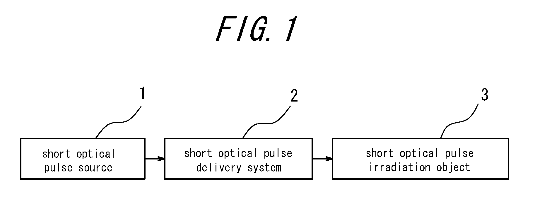
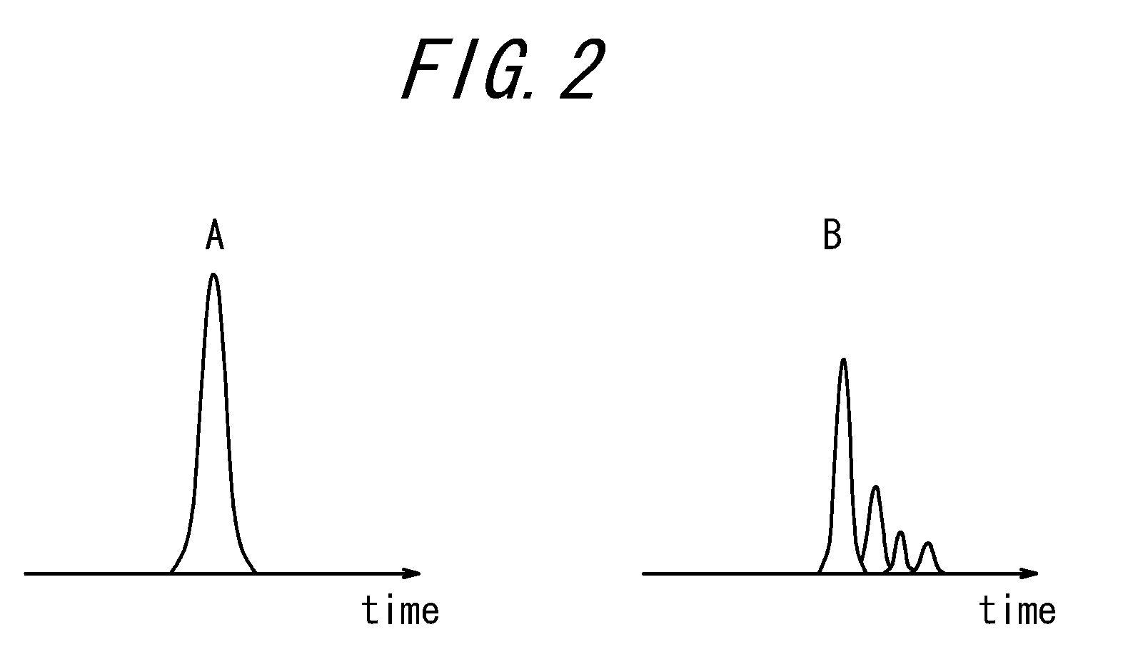
However, ultrashort optical pulses having high peak power are known to be temporally broadened and suffer waveform distortion in the process of propagating through the short optical pulse delivery system, due to the group-velocity dispersion (GVD) effects in the short optical pulse delivery system and the nonlinear optical effects such as a self-phase modulation (SPM) effects induced in the short optical pulse delivery system.
Such temporal broadening of optical pulses and waveform distortion of optical pulses lead to problems in many applications.
For example, in a nonlinear optical microscope such as a multiphoton fluorescence microscope, which requires ultrashort optical pulses having high peak power, if the pulses are temporally broadened or the pulses suffer waveform distortion in a short optical pulse delivery system such as an optical fiber, the short optical pulses are reduced in peak power accordingly, leading to a reduction in efficiency in multiphoton excitation, which results in a problem that the microscope image is reduced in brightness.
Meanwhile, the nonlinear optical effects are particularly noticeable when the short optical pulse delivery system includes a lengthy optical fiber, which requires specific measures to be taken.
Except for such a case, however, the nonlinear optical effects hardly result in a problem.

Method used


Image

  • Nonlinear optical device, multiphoton microscope, and endoscope
  • Nonlinear optical device, multiphoton microscope, and endoscope
  • Nonlinear optical device, multiphoton microscope, and endoscope

Examples


first embodiment

[0107]FIG. 4 is a schematic configuration diagram of a compact microscope nonlinear optical device 10 according to a first embodiment of the present invention. This embodiment includes a microscope downsized as a micro head 14, which is fixed to the head of a small laboratory animal such as a mouse, so as to observe an organ such as a mouse brain without anesthesia.

[0108]The compact microscope nonlinear optical device includes: a short optical pulse source 11 for generating chirped Gaussian short optical pulses; a lens 12; a hollow core photonic crystal fiber 13; the micro head 14; a multi-mode optical fiber 15; a lens 16; a barrier filter 17; and a detector 18.

[0109]The short optical pulse source 11 is for emitting chirped short optical pulses, and configured, for example, as a light source using a titanium: sapphire laser for generating Gaussian short optical pulses having a wavelength of 800 nm in the near-infrared region. The short optical pulse source 11 emits chirped short opt...

second embodiment

[0141]FIG. 7 is a schematic configuration diagram of an endoscope nonlinear optical device 20 according to a second embodiment of the present invention. This embodiment is different from the first embodiment of FIG. 4 in that the micro head 14 is formed as a hard part 21 and the hollow core photonic crystal fiber 13 and the multi-mode fiber 15 connected to the hard part 21 are bundled together into one so as to be configured as a flexible insertion part 22. The flexible insertion part 22 may be used alone or may be inserted into a clamp hole of a conventional endoscope, to thereby use the device as an endoscope nonlinear optical device 20. With this configuration, the device can be configured as an endoscope nonlinear optical device and still can produce the similar effects as in the first embodiment.

third embodiment

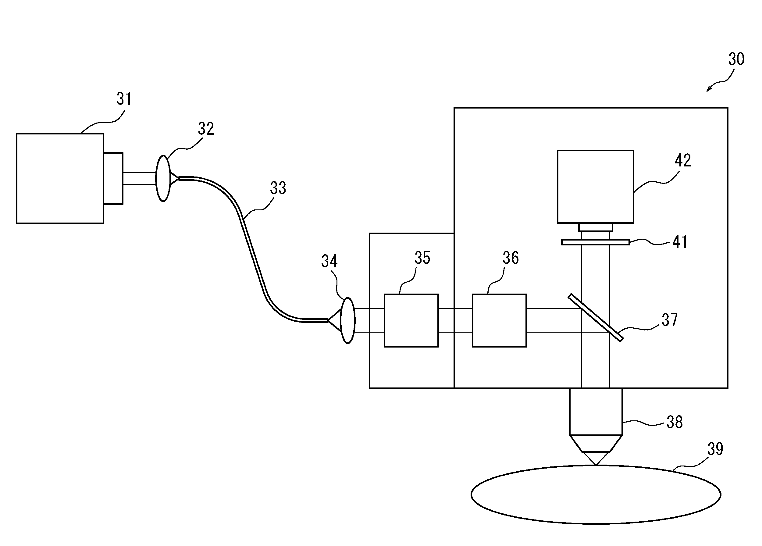
[0142]FIG. 8 is a schematic configuration diagram of a microscope nonlinear optical device 30 according to a third embodiment of the present invention. The microscope nonlinear optical device 30 is configured by including: a short optical pulse source 31 for generating sech short optical pulses; a lens 32; a hollow core photonic crystal fiber 33; a lens 34; a dispersion generator 35; a Galvano mirror 36; a spectral mirror 37; an objective lens 38; a barrier filter 41; and a detector 42.

[0143]The short optical pulse source 31 is configured, for example, as a light source using a titanium: sapphire laser for generating sech short optical pulses having a wavelength of 1030 nm in the near-infrared region. The short optical pulse source 31 emits chirped short optical pulses, with an average power of 0.5 W, a repetition frequency of 80 MHz, a temporal width (full width at half maximum) of 370 fs, and a spectral width (full width at half maximum) of 11 nm.

[0144]The lens 32, the hollow core...


PUM

PropertyMeasurementUnit
spectral widthaaaaaaaaaa
temporal widthaaaaaaaaaa
wavelengthaaaaaaaaaa

Abstract

Provided is a nonlinear optical device capable of alleviating, without the need for a complicated compensation mechanism, temporal broadening and the waveform distortion resulting from a group-velocity dispersion slope, to thereby irradiate an object with short optical pulses having high peak power. The nonlinear optical device includes a short optical pulse source (10) for generating short optical pulses and a short optical pulse delivery system (20) for delivering the short optical pulses generated from the short optical pulse source to an object, in which there is generated substantially no nonlinear optical effect and there is substantially no amount of group-velocity dispersion, the short optical pulse source generates short optical pulses, and the short optical pulses have a spectral width (full width at half maximum) λFWHM satisfying λ1<λFWHM<λ2.

Description

CROSS-REFERENCE TO RELATED APPLICATION[0001]The present application claims priority from Japanese Application No. 2011-207030, filed on Sep. 22, 2011, and from Japanese Application No. 2011-058053, filed on Mar. 16, 2011, the contents of which are incorporated herein by reference.TECHNICAL FIELD[0002]The present invention relates to a nonlinear optical device for irradiating an object with short optical pulses so as to induce second-order nonlinear optical effects, and also relates to a multiphoton microscope and endoscope using the nonlinear optical device.RELATED ART[0003]In recent years, sub-picosecond ultrashort optical pulses, having high peak power and a plurality of wavelength components, have been used in various fields, such as biology, medicine, medical care, processing, and measurement. In particular, in the fields of biology and medicine, an optical pulse source that generates ultrashort optical pulses, such as a titanium: sapphire laser and a fiber laser, has been frequ...

Claims


Application Information

Patent Timeline
Patent Type & Authority Patents(United States)
IPC IPC(8): H01S3/10A61B5/00G01N21/63G01N21/64G02B21/00G02B21/06G02B23/24H01S3/00
CPCG01N21/6458A61B5/0075G01N21/636G02B21/06G02B23/2469G02B21/0008G01N2201/0697H01S3/0057
Inventor FUJIWARA, MASATOTAIRA, KENJI
Owner OLYMPUS CORP
Learn More