Conical graphite electrode with raised edge

a graphite electrode and raised edge technology, applied in silicon compounds, cell components, coatings, etc., can solve the problems of high frequency of collapse before, high thermal dissipation risk in the reactor, and high thermal dissipation of electrodes, so as to improve thermal dissipation and improve current density distribution

Active Publication Date: 2015-10-06
WACKER CHEM GMBH
View PDF15 Cites 5 Cited by
  • Summary
  • Abstract
  • Description
  • Claims
  • Application Information

AI Technical Summary

Benefits of technology

[0029]With the electrode according to the invention, having a raised edge, a smaller temperature gradient is set up from the middle to the rod surface than in comparison with an electrode having a standard shape. Thermal stresses, which are relaxed by forming cracks and fractures, are therefore minimized compared with a rod foot having a conventional electrode. The smaller temperature gradient in the rod foot with an electrode according to the invention is achieved by a more uniform current density and better thermal dissipation, both of which are ensured by the raised edge.

Problems solved by technology

Long and thick polycrystalline silicon rods increase the economic viability of the deposition process, but also the risk of collapse in the reactor.
A disadvantage with this embodiment is a high frequency of collapse before and during the deposition until the final diameter is reached.
This electrode shape has very high thermal dissipation even with a small rod diameter, owing to the solid cylindrical shape.
Thick rods, as are customary nowadays, cannot be deposited with this electrode shape since, owing to the small electrode diameter and the low specific thermal conductivity of the electrode material, the high energy required for thick rod diameters cannot be dissipated from the rod feet.
A disadvantage with all electrodes known from the prior art is that they are relatively susceptible to cracking or flaking of material at the transition between the electrode and the silicon rod or in the silicon rod, in the vicinity of the electrode, so that they make the silicon rod unstable.
Collapsed batches entail great economical loss.
If the silicon rods collapse, for example, the reactor wall may be damaged.
The surface of the silicon is then further contaminated.

Method used


Image

  • Conical graphite electrode with raised edge
  • Conical graphite electrode with raised edge
  • Conical graphite electrode with raised edge

Examples


example 1

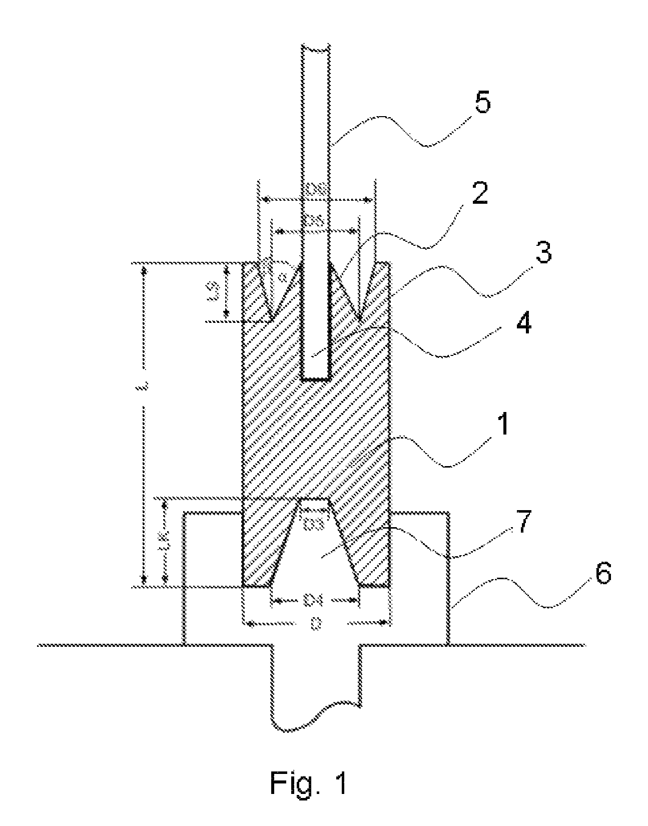
[0075]Electrodes according to the invention with a raised edge, as represented in FIG. 1, were used for the deposition. In addition, a heat sink was used on the base of the electrode. The electrodes used consisted of ultrapure electrographite with a specific thermal conductivity of 80 W / (m*K) and an electrical resistivity of 15 μohm*m.

[0076]The electrode had the following geometry:

[0077]

total length (L):118 mm diameter (D):65 mmcone angle (α):32°cone angle (β):16°electrode tip length (LS):21 mmelectrode tip diameter (D5):34 mminner edge diameter (D6):46 mmheat sink diameter (D3):25 mmheat sink diameter (D4):45 mmheat sink length (LK):50 mm

[0078]At the end of the reaction, the reactor was opened and the number of batches with collapsed polysilicon rods was noted. Out of 100 batches, 2 batches had collapsed after reaching the final diameter but no batches had collapsed before reaching the final diameter during the deposition.

example 2

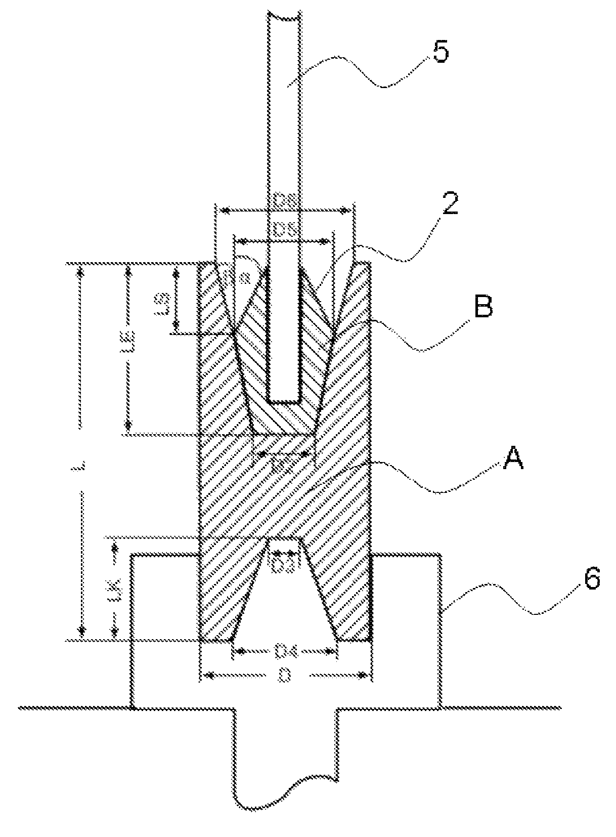
[0079]Electrodes according to the invention with a raised edge, which consisted of 2 different zones with different specific thermal conductivity (see FIG. 3), were used for the deposition. In addition, a heat sink was used on the base of the electrode. Zone (A) of the electrodes used consisted of ultrapure electrographite with a specific thermal conductivity of 135 W / (m*K) and an electrical resistivity of 10 μohm*m. For the inner zone (B), an ultrapure electrographite with a specific thermal conductivity of 50 W / (m*K) and an electrical resistivity of 22 μohm*m was used.

[0080]The electrode had the following geometry:

[0081]

total length (L):118 mm diameter (D):65 mmcone angle (α):32°cone angle (β):16°electrode tip length (LS):21 mmelectrode tip diameter (D5):34 mminner edge diameter (D6):46 mminsert length (LE):46 mminsert diameter (D1):34 mminsert diameter (D2):22 mmheat sink diameter (D3):25 mmheat sink diameter (D4):45 mmheat sink length (LK):50 mm

[0082]At the end of the reaction, ...

example 3

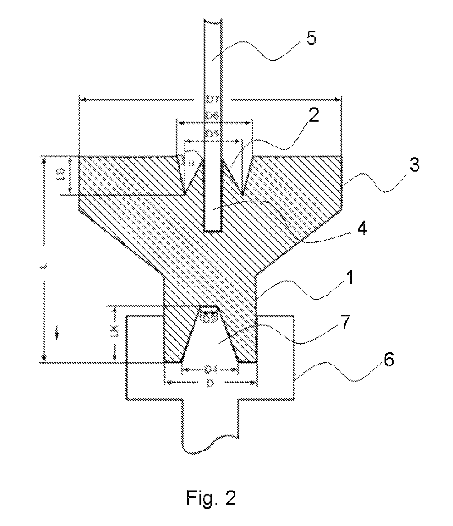
[0083]Electrodes according to the invention with a raised edge were used for the deposition. In addition, the upper edge of this electrode was widened (see FIG. 2).

[0084]In addition, a heat sink was used on the base of the electrode. The electrodes used consisted of ultrapure electrographite with a specific thermal conductivity of 80 W / (m*K) and an electrical resistivity of 15 μohm*m.

[0085]The electrode had the following geometry:

[0086]

total length (L):118 mm diameter (D):65 mmcone angle (α):32°cone angle (β):16°electrode tip length (LS):21 mmelectrode tip diameter (D5):34 mminner edge diameter (D6):46 mmwidened edge diameter (D7):130 mm heat sink diameter (D3):25 mmheat sink diameter (D4):45 mmheat sink length (LK):50 mm

[0087]At the end of the reaction, the reactor was opened and the number of batches with collapsed polysilicon rods was noted. Out of 100 batches, 1 batch had collapsed after reaching the final diameter, but no batches had collapsed before reaching the final diameter...


PUM

PropertyMeasurementUnit
roughnessaaaaaaaaaa
roughnessaaaaaaaaaa
roughnessaaaaaaaaaa

Abstract

A carbon electrode has a conical or pyramidal tip, wherein the tip is surrounded on its side by a raised edge.

Description

BACKGROUND[0001]The invention relates to a carbon electrode having a conical or pyramidal tip, which is surrounded on its side by a raised edge.[0002]Graphite electrodes are used in many different applications in industry. Examples of these are aluminum and steel production, electrolysis of salt melts, electrolytic decomposition of chemical compounds, thermal deposition reactions, arc welding, measuring instruments and many others.[0003]One important application is the deposition of polysilicon by the Siemens process, in which highly pure elementary silicon is deposited from the gas phase on the surface of silicon rods. In this case, elemental silicon is deposited from a mixture of hydrogen and halosilanes, or a silicon compound containing hydrogen, in the gas phase, onto the surface of a thin silicon rod heated to from 900 to 1200° C. in a deposition reactor.[0004]The silicon rods are held in the reactor by special electrodes, which generally consist of highly pure electrographite....

Claims


Application Information

Patent Timeline
Patent Type & Authority Patents(United States)
IPC IPC(8): H05B7/06C23C16/00C01B33/035
CPCC01B33/035C25B1/33C25B11/043Y02E60/50C01B32/21H01B1/04H01M4/96
Inventor KRAUS, HEINZ
Owner WACKER CHEM GMBH
Why Eureka
Try Eureka