
Polishing pad and method for producing same

a technology of polishing pad and dummy polishing time, which is applied in the field of polishing pads, can solve the problems of low durability of polishing pads, low stability of polishing rate, and gradual deformation of planarization performance, and achieves high thickness precision, high polishing rate, and shortening of break-in time (dummy polishing time)

Active Publication Date: 2015-10-13
ROHM & HAAS ELECTRONICS MATERIALS CMP HLDG INC
View PDF30 Cites 4 Cited by
  • Summary
  • Abstract
  • Description
  • Claims
  • Application Information

AI Technical Summary

Benefits of technology

The invention provides a polishing pad that has a high polishing rate and thickness precision, which reduces break-in time. To achieve this, the invention uses a thermoset polyurethane foam with interconnected cells that act as a polishing layer. This foam has improved durability and stability compared to conventional polishing pads. The polishing layer is self-bonded to the base material layer to prevent peeling during polishing. Overall, this invention provides a long-lasting and effective polishing pad for high performance polishing.

Problems solved by technology

Unfortunately, conventional polishing pads have a problem in which since they have a long, thin cell structure or a surface layer made of a material with low mechanical strength, their durability is low so that the planarization performance is gradually degraded or they have low polishing rate stability.
Conventional polishing pads also have a problem in which cells are often clogged with polished debris (particularly pad debris) so that they have low stability of polishing characteristics and a short life.

Method used


Image

  • Polishing pad and method for producing same
  • Polishing pad and method for producing same

Examples


example 1

[0107]To a vessel were added 55 parts by weight of polycaprolactone triol (PCL305 manufactured by DAICEL CHEMICAL INDUSTRIES, LTD., 3 in the number of functional groups, 305 mgKOH / g in hydroxyl value), 30 parts by weight of polytetramethylene ether glycol (PTMG 1000 manufactured by Mitsubishi Chemical Corporation, 2 in the number of functional groups, 112 mgKOH / g in hydroxyl value), 13 parts by weight of diethylene glycol (DEG, 2 in the number of functional groups, 1,058 mgKOH / g in hydroxyl value), 2 parts by weight of trimethylolpropane (TMP, 3 in the number of functional groups, 1,255 mgKOH / g in hydroxyl value), 6 parts by weight of a silicone surfactant (B8443 manufactured by Goldschmidt A. G.), and 0.03 parts by weight of a catalyst (Kao No. 25 manufactured by Kao Corporation) and mixed. The reaction system was vigorously stirred for about 4 minutes with a stirring blade at a rotational speed of 900 rpm so that air cells were incorporated into the reaction system. Thereafter, 10...


PUM

PropertyMeasurementUnit
average cell diameteraaaaaaaaaa
storage modulusaaaaaaaaaa
hydroxyl valueaaaaaaaaaa

Abstract

An object of the invention is to provide a polishing pad that achieves a high polishing rate and has high thickness precision so that the break-in time (dummy polishing time) can be shortened, and to provide a method for producing same. The invention is directed to a polishing pad including a base material layer and a polishing layer provided on the base material layer, wherein the polishing layer includes a thermoset polyurethane foam having roughly spherical interconnected cells with an average cell diameter of 35 to 200 μm, and the polishing layer has a storage modulus E′ (40° C.) of 130 to 400 MPa at 40° C., a ratio of storage modulus E′ (30° C.) at 30° C. to storage modulus E′ (60° C.) at 60° C. [E′(30° C.) / E′(60° C.)] of 1 to less than 2.5, and a ratio of storage modulus E′ (30° C.) at 30° C. to storage modulus E′ (90° C.) at 90° C. [E′(30° C.) / E′(90° C.)] of 15 to 130.

Description

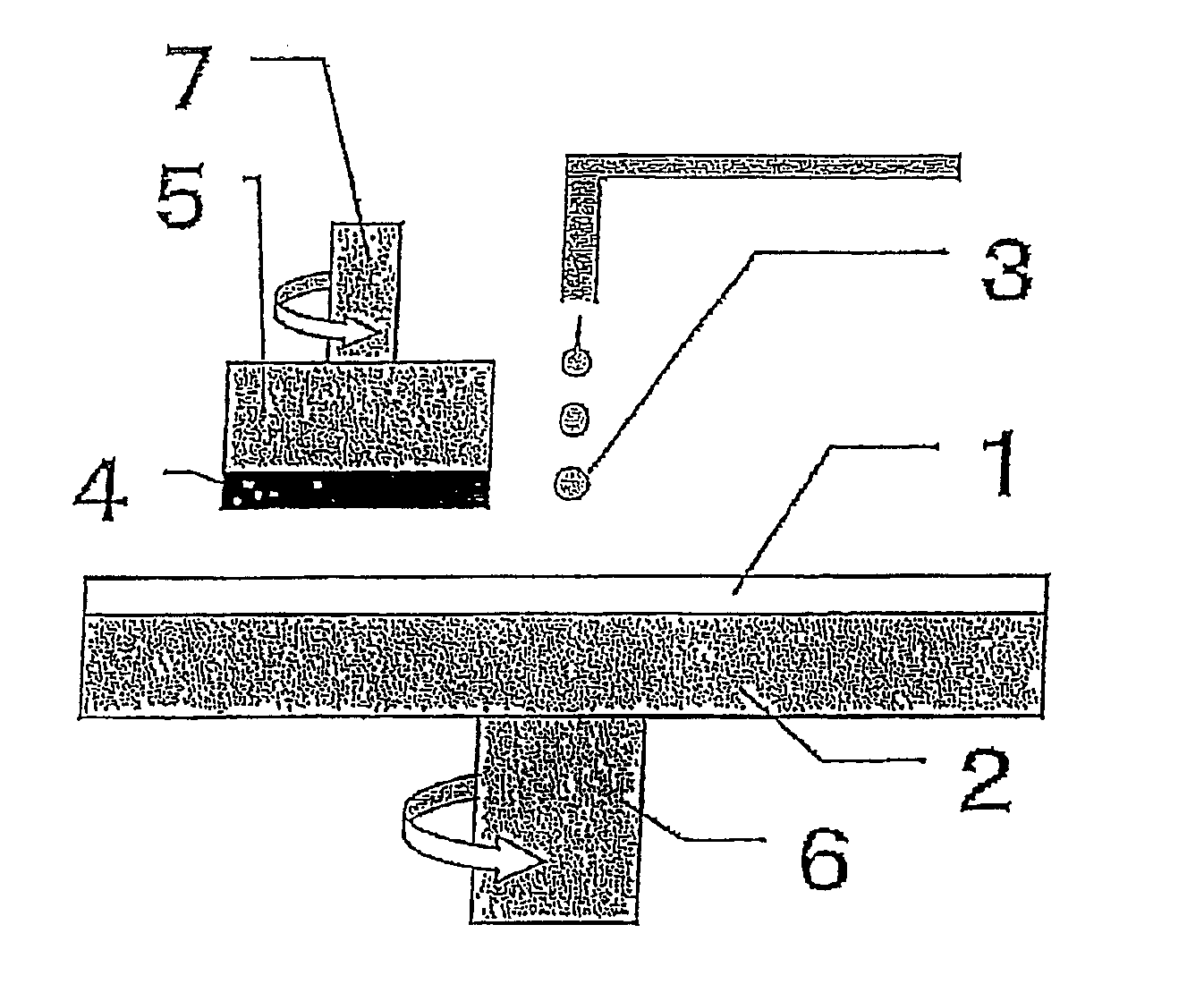
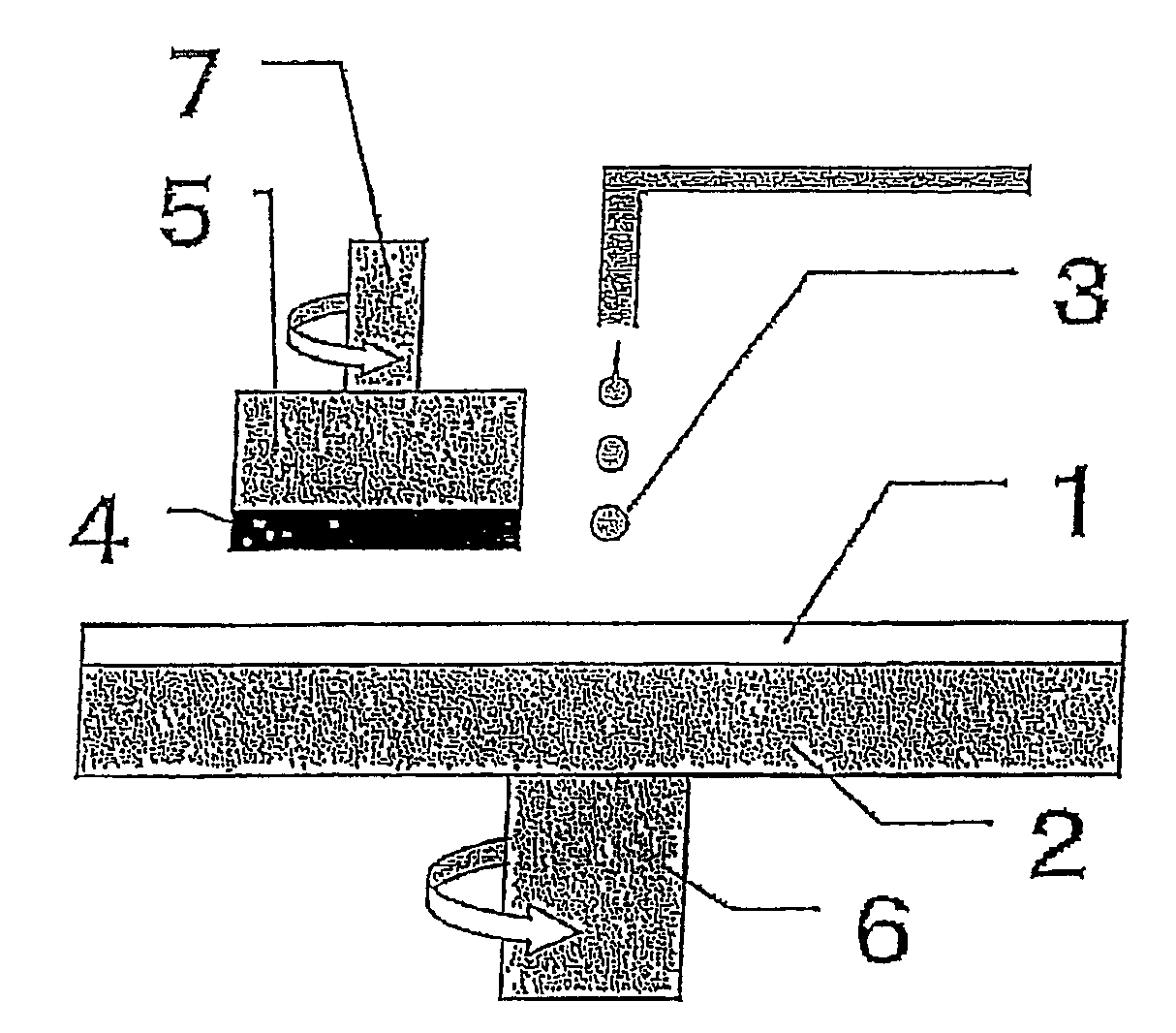
TECHNICAL FIELD[0001]The present invention relates to a polishing pad (for rough polishing or for final polishing), which is used upon polishing of a surface of optical materials such as lenses and reflection mirrors, a glass substrate for silicon wafers and hard disks, and an aluminum substrate. Particularly, the polishing pad of the present invention is suitably used as a polishing pad for finishing.BACKGROUND ART[0002]Generally, the mirror polishing of semiconductor wafers such as a silicon wafer etc., lenses, and glass substrates includes rough polishing primarily intended to regulate planarity and in-plane uniformity and final polishing primarily intended to improve surface roughness and removal of scratches.[0003]The final polishing is carried out usually by rubbing a wafer against an artificial suede made of flexible urethane foam stuck to a rotatable platen and simultaneously feeding thereon an abrasive containing a colloidal silica in an alkali-based aqueous solution (Paten...

Claims


Application Information

Patent Timeline
Patent Type & Authority Patents(United States)
IPC IPC(8): B32B3/00B32B3/26B24D11/00B24B37/24C08G18/00C08G101/00H01L21/304
CPCB24B37/24Y10T428/249978B24D3/26
Inventor FUKUDA, TAKESHIISHIZAKA, NOBUYOSHI
Owner ROHM & HAAS ELECTRONICS MATERIALS CMP HLDG INC
Learn More