Fluidic channel coated with metal catalysts and devices and methods relating thereto

a technology of metal catalysts and fluidic channels, applied in physical/chemical process catalysts, metal/metal-oxide/metal-hydroxide catalysts, laboratory glassware, etc., can solve the problems of inability to obtain high quality, coating fluidic channels, etc., and achieve the effect of enhancing catalytic activity

Active Publication Date: 2015-12-15
MILLIFLUIDICA
View PDF15 Cites 0 Cited by
  • Summary
  • Abstract
  • Description
  • Claims
  • Application Information

AI Technical Summary

Benefits of technology

[0007]The invention provides devices having catalyst coatings within fluidic channels in a controlled manner. The control is seen in at least three significant ways. First, the coating dimensions can be controlled. This includes both the size of catalytic nanostructures, and the area over which they are grown throughout the millifluidic channels. Second, the growth location of the catalytic coating can be controlled. For example, FIG. 1A-C show a thin strip of gold catalyst coating within the center of channels having a width of approximately 200 microns. Catalytic coatings can also be grown throughout the entire channel by varying conditions such as flow rate, precursor injection location, and other variables which affect the flow system's Reynolds number. Third, the morphology of the catalyst coating can be controlled with micro and nanoscopic precision. Petalled flower-like structures, half-hemisphere structures, porous surfaces, and permutations thereof are among the achievable morphologies which enhance catalytic activity, as can be seen in FIG. 2. The reactants, which react catalytically with the catalyst, can flow through the channels and the product is obtained at the outlet without any clogging due to the millifluidic scale of the channels and the size of nanostructures grown within. The invention thus provides a method for coating fluidic channels with catalysts having controlled dimensions and morphology.

Problems solved by technology

However, a major drawback of microfluidic chips is the inability to obtain high quality data from techniques such as in situ XAS for sample concentration in excess of 0.1 M. Thus, new techniques and devices are needed to overcome these drawbacks.
Additionally, there are problems in coating fluidic channels with catalysts having controlled dimensions and morphology.

Method used


Image

  • Fluidic channel coated with metal catalysts and devices and methods relating thereto
  • Fluidic channel coated with metal catalysts and devices and methods relating thereto
  • Fluidic channel coated with metal catalysts and devices and methods relating thereto

Examples


example 1

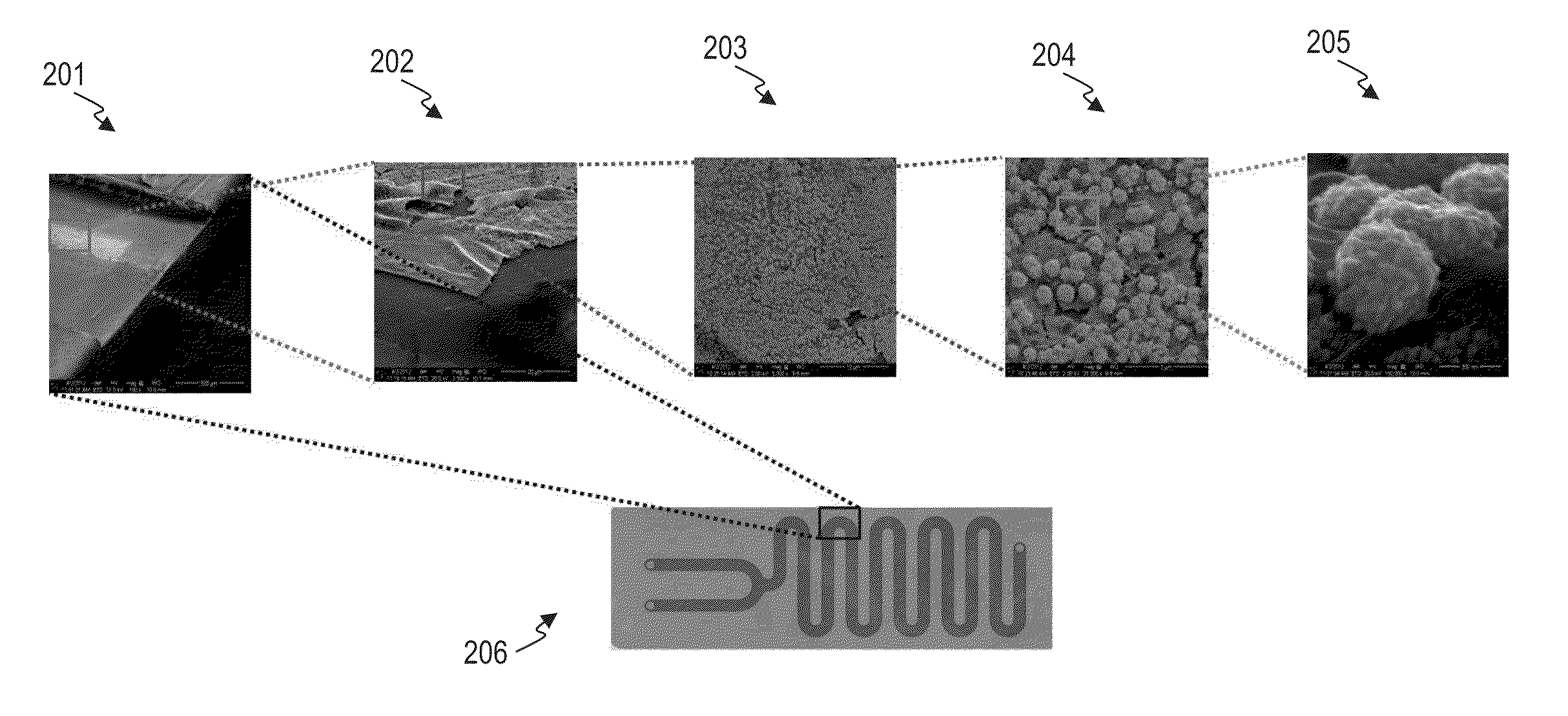
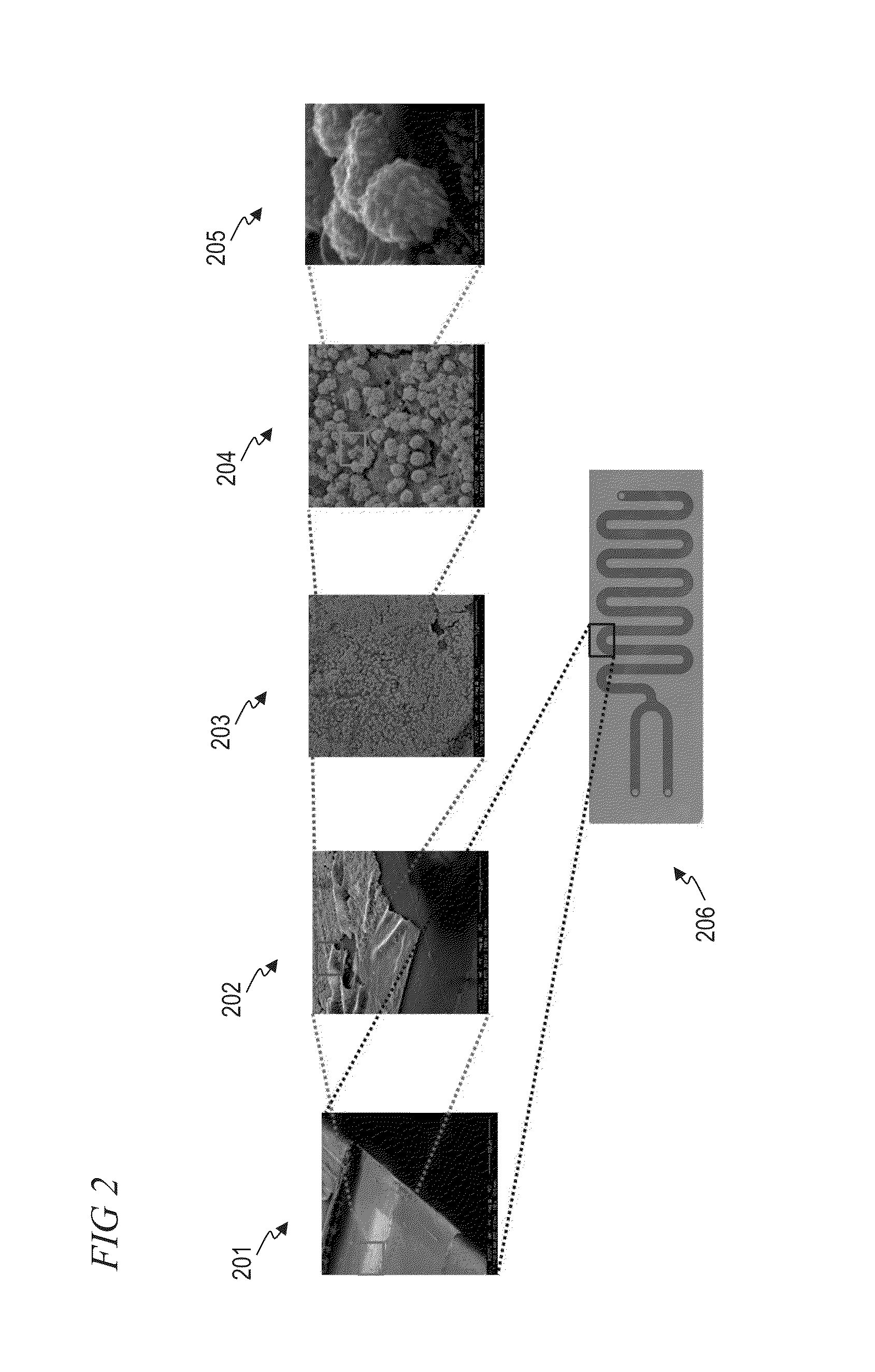
Catalyst Coating Method: Time Dependent Formation of Gold Nanostructures

[0140]Millifluidic chips (made of polyester terephthalate polymer) were purchased from Microplumbers Microsciences LLC. The chip had serpentine channels with dimensions of 2 mm (W)×0.15 mm (H)×220 mm (L) within which the experiments were performed. High precision, fully automated, pulsation free syringe pumps to flow the liquids within the chip were purchased from Cetoni Automation and Microsystems, GmbH. Fluidic connections between the reactor chip and the pump were made using FEP tubing (0.25 mm I.D., 1 / 16″ O.D., Dolomite). The pumps were tested with water as solvent at different flow rates prior to the experiment to optimize the required flow rate. HAuCl4 (Aldrich, 99.9%), meso-2, 3-dimercaptosuccinic acid (DMSA, Aldrich, 98%), NaBH4 (Aldrich, 98%), and Nanopure water (18.2 MΩ-cm) was used in all experiments (Examples 1 and 2).

[0141]A Standard solution of gold chloride (10 mM) was prepared by dissolving 118.2...

example 2

Catalytic Reaction in a Catalyst Coated Flow Channel

[0154]15 mL of 9×10⁻² mM solution of 4-nitrophenol was mixed with 3.3 mL of 0.65 M NaBH4 solution to form phenolate ions. This resultant solution was passed through the prepared gold catalyst coated within the flow channels (as described in Example 1) and the product was collected, to complete the reduction of 4-nitrophenol to 4-aminophenol catalyzed by gold, as illustrated in Scheme 2.

[0155]

Two catalysis reactions, (1) 4-nitrophenol reduction to 4-aminophenol and (2) hexacyanoferrate (III) reduction to hexacyanoferrate (II) were performed with three sets of gold catalysts (i.e. structures formed at 1 h, 5 h and 9 h respectively). In a typical reaction, 15 ml of 9×10⁻⁵ mol solution of 4-nitrophenol was mixed with 3.3 ml of 0.65 mol NaBH4 solution to form 4-nitrophenolate ion according to reported literature procedure.31 The resultant solution was passed through the gold structures deposited chip at 5 ml / h flow rate (other flow-rate...

example 3

Synthesis of Ultrasmall Copper Nanoclusters (UCNCs) in a Millifluidic Reactor

[0159]Chemicals used in this experiment include: Copper(II) nitrate hydrate (99.999%), sodium borohydride (≧98.0%), Sodium hydroxide pellets (99.998%) and O-[2-(3-Mercaptopropionylamino)ethyl]-O′-methylpolyethylene glycol (Mw 5000) [MPEG], fumed silica, styrene (≧99.0%), tert-Butyl hydroperoxide solution—packed in PTFE bottles, ˜5.5 M in decane (over molecular sieve 4 Å), anhydrous acetonitrile, methanol were obtained from Sigma-Aldrich. All chemicals were used as received without further purification. Water was supplied by a Barnstead Water Purifier Nanopure water system (18.3 MΩ cm).

[0160]A millifluidic chip (made of polyester terephthalate polymer) was purchased from Microplumbers Microsciences LLC, which has serpentine channels with dimensions of 2 mm (W)×0.15 mm (H)×220 mm (L). Use FEP Tubing (purchased from Dolomite Centre) with dimensions of 0.25 mm I.D., 1 / 16″ O.D., for connecting the chip to the pu...


PUM

PropertyMeasurementUnit
widthaaaaaaaaaa
diametersaaaaaaaaaa
widthaaaaaaaaaa

Abstract

The invention provides a method for coating fluidic channels, particularly millifluidic channels, with a catalyst coating having controlled dimensions and morphology, and methods for preparing such channels, and devices that can be used in combination with the channels. The invention further provides portable, hand-held millifluidic devices applicable for a wide variety of uses including molecular reduction reactions, in situ material characterization, in situ reaction catalysis characterization, in situ reaction mechanism characterization, nanomaterial synthesis, nanostructured metal and metal oxide growth and coating of channels, continuous flow cell culturing, enzymatic catalysis, biomolecular catalysis, combinatorial chemistry, reactions involving homogeneous catalysts bound to channel walls, peptide synthesis, nucleic acid synthesis, synthesis of pharmaceutical intermediates, biofunctionalization of nanomaterials or a combination thereof.

Description

RELATED APPLICATIONS[0001]This application claims priority under 35 U.S.C. §119(e) to U.S. Provisional Patent Application No. 61 / 703,085, filed Sep. 19, 2012, which is incorporated herein by reference.BACKGROUND OF THE INVENTION[0002]A number of synchrotron radiation-based X-ray characterization tools are used for both chemical and physical characterization of materials, especially in a liquid environment. Among these, X-ray absorption spectroscopy (XAS) is a versatile tool to probe oxidation states, coordination, and local order of materials, even in the absence of a crystalline lattice. XAS has been used to investigate the electronic and geometric structures of nanomaterials; more specifically, to map local coordination number, the extent of alloying and composition of multi-metallic systems in solution. Further, in situ XAS offers an opportunity to observe time-resolved bond formation, changes in oxidation states, coordination, and local order. The ability to follow the fundament...

Claims


Application Information

Patent Timeline
Patent Type & Authority Patents(United States)
IPC IPC(8): B01J19/24B22F9/18C07C213/02B01J19/00B01L3/00B01J37/02B22F9/24B82Y40/00B82Y30/00B01J35/00B22F1/00B01J37/16B01J37/18B01J23/42B01J23/44B01J23/46B01J23/50B01J23/72B01J23/745B22F1/054
CPCB01J19/0093B01J19/24B01J37/0215B01L3/5027B01L3/502707B22F9/18B22F9/24C07C213/02C07C215/76B01J23/42B01J23/44B01J23/464B01J23/50B01J23/72B01J23/745B01J35/006B01J35/0013B01J37/16B01J37/18B01J2219/0086B01J2219/00792B01J2219/00835B01J2219/00858B01J2219/00862B01J2219/248B01J2219/2479B01L2300/0816B01L2300/0867B01L2300/0883B01L2300/16B01L2300/161B01L2400/0487B22F1/0018B22F2001/0037B82Y30/00B82Y40/00C12M23/06B22F1/0553B22F1/054
Inventor CHALLA, SIVA SAI RAMANA KUMAR
Owner MILLIFLUIDICA
Why Eureka
Try Eureka