Power assistance bicycle using sensor having multiple magnet blocks evenly distributed in housing

a technology of magnet block and power assistance, which is applied in the direction of instruments, code conversion, transportation and packaging, etc., can solve the problems of not meeting the control effect cannot meet the requirements of people's assistance, and the use of flexible assembly is not durable, so as to achieve the effect of satisfying the starting and running model

Inactive Publication Date: 2016-06-07
CHENGDU KUANHE TECH +3
View PDF9 Cites 3 Cited by
  • Summary
  • Abstract
  • Description
  • Claims
  • Application Information

AI Technical Summary

Benefits of technology

[0105]Advantages of the present invention are: a simple structure, a low cost, no quantity limit for the permanent magnetic blocks on a permanent magnetic block ring, outputting standard pulse signals, no signal blind area, fully representing all moving stats of a moving disk only by one Hall element and a set of output signals, no distortion and drift of the output signals, being adaptable for power assistance bicycle, and comforting a rider by highly cooperating power assistance output with power assistance requirements.
[0106](1) the simple structure, no elastic member, no mechanical failure: the Hall element senses the rotating output signals of a plurality of permanent magnetic blocks; with a speed-to-moment principle provided by a Chinese patent 01201843.0, moment parameters of the power assistance bicycle are able to be calculated by a variety of mathematical models, so as to control the motor of the power assistance bicycle for power assistance; no elastic part is utilized, the structure is simple, and the cost of the present invention is lower than that of sensors using the elastic parts and mechanical force bearing; deformation of each mechanical part after long-term use is avoided, no mechanical failure and cooperating problem exist.
[0107](2) the opposite magnetic polarities, outputting the rectangular wave signals, and the precise controlling function: because the adjacent two permanent magnetic blocks have opposite magnetic polarities and the Hall element generating rectangular wave output signals according to the opposite polarities is utilized, no matter how narrow an interval is between the two adjacent permanent magnetic blocks, even if there is no gap, the Hall element is also able to output rectangular wave signals; if the sensor is utilized on the power assistance bicycle, the rectangular wave output signals are better than sine waves for controlling the power assistance bicycle, because by utilizing rectangular waves, signals representing moving speeds are precise at any point and any time, so as to precisely represent moving speed of pedals of the power assistance bicycle, for calculating correct power assistance requirements for the moving state by a precise speed of the pedals.
[0108](3) the opposite magnetic polarities of the adjacent permanent magnetic blocks, no quantity limit for the permanent magnetic blocks, and increase sensing points as many as possible: because of the opposite magnetic polarities and the rectangular wave output signals, even if there is no gap between the adjacent permanent magnetic blocks, the output signals are still a plurality of distinguishable rectangular wave signals with the controlling function; that is to say, linear signals with no controlling function and no change will not be outputted; if the sensor is utilized on the power assistance bicycle, a size of the annular-groove rotating disk linked with the pedals is limited, and the permanent magnetic blocks and the sensing points are arranged as many as possible, in such a manner that the moving speeds of the pedals are represented by as many sensing signals as possible for precise representation of the moving state.
[0109](4) the opposite magnetic polarities of the adjacent permanent magnetic blocks, a large number of the permanent magnetic blocks and the sensing points, and the precise representation of the moving state of the annular-groove rotating disk: the size of the annular-groove rotating disk adapting to the power assistance bicycle for fixing the permanent magnetic blocks is strictly limited; usually a diameter thereof is no more than 10˜15 cm; for enabling the Hall elements to sense polarity signals of the permanent magnetic blocks with the intervals, a diameter of each of the permanent magnetic blocks is at least 0.6˜0.8 cm, and 35˜73 permanent magnetic blocks are able to be arranged without interval around the annular-groove rotating disk with the diameter of 10˜15 cm, wherein [(10−1)*3.14 / 0.8=35; (15−1)*3.14 / 0.6=73]; that is to say, after the pedal rotates once, the Hall element is able to obtain 35-73 signals for controlling the motor of the power assistance bicycle; however, according to the conventional technology where magnetic polarities of adjacent permanent magnetic blocks are the same, the adjacent permanent magnetic blocks having a 5 cm-interval; as a result, only 5˜8 permanent magnetic blocks are able to be arranged around the annular-groove rotating disk with a diameter of 10˜15 cm, wherein [(10−1)*3.14 / 5.8=5; (15−1)*3.14 / 5.6=8]; therefore, the permanent magnetic blocks of the present invention are 7˜9 times more than the permanent magnetic blocks of the conventional technology, wherein [35 / 5=6; 73 / 8=9]; which means 30˜65 more permanent magnetic blocks are provided, wherein [35−5=30; 73−8=65]; therefore, after the annular-groove rotating disk rotates once, rotating point signals of the annular-groove rotating disk of the present invention is 7˜9 times more than that of the conventional technology; as a result, motor control accuracy for a power assistance bicycle is naturally raised by 7˜9 times and power assistance accuracy for the rider is also increased by 7˜9 times, in such a manner that cooperation of the rider and the bicycle are greatly improved as well as rider comfort; uncomfortable feeling according to the conventional technology, which is sometimes fast and sometimes slow, no longer exists; according to actual experience of the applicant, when there are about 15 permanent magnetic blocks evenly provided on the annular-groove rotating disc, the feeling which is sometimes fast and sometimes slow due to 5˜8 permanent magnetic blocks of the conventional technology is basically eliminated; when there are about 20 permanent magnetic blocks evenly provided on the annular-groove rotating disc, the cooperation of the bicycle and the rider is able to satisfy the rider and the power assistance bicycle comfortable to ride.
[0110](5) no signal blind area, providing power assistance corresponding the power assistance requirements at any time: according to the present invention, at most 35˜73 permanent magnetic blocks are able to be arranged around the annular-groove rotating disk with the diameter of 10˜15 cm, and an average angle between the adjacent permanent magnetic blocks are 5˜10 degrees; if the sensor is utilized on the power assistance bicycle, during starting or running, there are 4˜7 permanent magnetic blocks in a 35-degree area determined by the pedal from 10 to 45 degrees away from an apex (at 10 degrees away from the apex there is a first signal), and the Hall element outputs 4˜7 controlling signals representing the power assistance requirements for achieving a excellent technical effect that the power assistance is available at anywhere and anytime as long as there is the power assistance requirement, in such a manner that the cooperation of the bicycle and the rider is sufficient and rider feels comfortable.
[0111](6) only one Hall element, one controlling signal representing all moving states of the annular-groove rotating disk, the controlling signal completely consistent with the moving state of annular-groove rotating disk, and the controlling signal completely consistent with rider requirements: a plurality of permanent magnetic blocks are mounted on the annular-groove rotating disk and synchronously rotate with the annular-groove rotating disk; by sensing the moving signals of all of the permanent magnetic blocks by one Hall element, the controlling signals outputted by the Hall element is completely consistent with the moving state of the annular-groove rotating disk as well as the rider requirements, and the controlling signals avoids initial segment errors and signal drift; Even if sensing parameters of the Hall element change, the controlling signals will move in parallel; as long as a receiving range of the motor receiving the Hall controlling signals is wide, a controlling effect of the changed controlling signals will systemically change, if the sensor is utilized on the power assistance bicycle, a power assistance requirement model will not be distorted, power assistance output and the power assistance requirements remain an original model matching relationship, wherein the rider can easily handle the systemic change of power assistance performance.
[0112](7) a housing is formed by the relative-rotating annular-groove rotating disk and the annular-groove fixing disk, which fixes relative positions of the Hall element and all of the permanent magnetic blocks for avoiding external environment interference, improving reliability and authenticity of the Hall signals, and facilitating installation, commissioning as well as maintenance.
[0113](8) digitization for the Hall signals, so as to transform digital signals into the power assistance model digital signals with rotating velocity of the rotating disk, then the power assistance model digital signals are transformed into the power assistance model analog signals, and finally the power assistance model analog signals are transformed into the controlling signals suitable for the motor controller with a stable voltage range and rated power; in short, the magnetic block rotation signals digitalized, and during the digitalization, the mathematical power assistance model is added, in such a manner that the power assistance model is comprised in the final controlling signals outputted by the sensor; because the mathematical power assistance model is artificial, the mathematical power assistance model is always able to be set to the preferred man-machine model, in such a manner that the sensor according to the present invention is able to output man-machine controlling signals; however, according to the conventional sensor for the power assistance bicycle, same polarities of different permanent magnetic blocks are at the same side; therefore, the Hall element cannot obtain the rectangular wave signals, and the Hall signal cannot be digitized, wherein a control model of the conventional sensor is only able to partly modify the Hall signals, which cannot output the man-machine controlling signals.
[0114](9) no signal drift for the last controlling signals: the thermal resistor R6 provides feedback regulation for the output signals of the operational amplifier, which is able to the solve an analog signal drift problem of the power assistance model due to semiconductor devices such as the Hall element, the digital-to-analog converter and the operational amplifier, in such a manner that the sensor finally outputs the standard power assistance model analog signals which are not affected by the environment temperature changes.
[0115]The operation mode capable of achieving man-machine matching is as follows. The power assistance model calculator utilizes the power assistance mathematical model cooperated with the power assistance requirements in the power assistance model storage and parameter of velocity provided by the magnetic block rotation velocity calculator is substituted into the power assistance mathematical model, so the power assistance model calculator is capable of calculating power assistance model digital signals which are a control signals for controlling the motor and capable of matching the rider and the bicycle. The power assistance model calculator is a digital processor which is capable of reserving any digital mathematical model, so the power assistance model storage is capable of providing the power assistance model calculator with any artificial mathematical model. U Under the condition of randomly setting mathematical model, people can set a mathematical model matching the rider and the electric motor. Since the power assistance model storage has inartificially set and capable of matching the rider and the electric bicycle, the cooperated operation manner of the rider and the electric bicycle is achieved. The artificially set mathematical model can also make the motor have a satisfying starting and running model and a power conservation operation manner. Thus, the power-assistance bicycle of the present invention is a power conservation power-assistance bicycle cooperated by the rider and the electric bicycle.
[0116](10) In one rotation period of the pedal of the conventional power-assistance bicycle, the Hall element is only capable of outputting less than 10 sinusoidal wave signals. The sinusoidal wave signals can not be transformed into digital signals and can not be added to the motor of the electric bicycle controlled by the power-assisted model. The power-assisted model of this kind of power assistance bicycle is not capable of achieving man-machine matching, and not capable of providing a satisfying and power conservation manner of working for the motor.
[0117](11) Power conservation effects and significances are as follows. The power-assistance bicycle of the present invention is compared with power-assistance bicycle with a sensor having 8 permanent magnetic blocks on an identical surface as an identical magnetic pole which is purchased in the market. The method of changing different sensors on one electric bicycle is utilized, and a same rider rides the electric bicycle on an identical section of road for testing. The result is as follows. After riding the power-assistance bicycle of the present invention for 110 kilometers, the battery still has a small amount of power. After riding the power-assistance bicycle purchased on the market for 45 kilometers, the battery is power off. The significances of power conservation lies in that the fully charged power-assistance bicycle of the present invention is capable of being rided for a whole day without battery charging, which solves the great problems of the conventional power-assistance bicycle of not capable of providing power assistance on the way.

Problems solved by technology

After a long time utilization, changes of spring constants of the flexible assembly lead to changes of control effects of the sensing signal and the controlled motor, so that the control effects can not meet the requirements of people's assistance.
In addition, the flexible assembly has a complicated structure and a high cost.
The flexible assembly utilized is not durable.
After a time of utilization, changes of spring constant of the flexible assembly lead to control effect changes of the controlled motor, so that the control effects can not meet the requirements of people's assistance.
In addition, the flexible assembly has a complicated structure and a high cost.
The sine wave outputted allow a disc group edge distance of not less than 4 cm, and preferably 5 cm, which causes a result that the number of the magnetic sheet groups are too few and that the man-machine cooperation is not satisfying.
In other words, when the technical solution of the patent application of 01201843.0 is utilized in a power assistance bicycle, the number of the magnetic sheet groups is limited to 8, the number of the control signal is too few and the man-machine cooperation is not satisfying.
The signal does not have a control function and is not capable of controlling the motor, so that when the assistance power is particularly required, the power assistance function is lost.
The blind zone of the signal has a blind angle of 45 degrees, and the assistance power can not be obtained when required in starting.
And the result is that the motor of the power assistance bicycle is not capable of providing assistance power while requiring the assistance power most.
In summary, except that the flexible assembly is not durable and has complicated structures, the diameter of the wheel is within 20 cm, which limits the number of the magnetic sheet group to 8.
Thus, the groups of the magnetic sheets can not be added optionally, the man-machine cooperation is not satisfying, the assistance power is not available while starting.
The assistance power can not meet the requirements.
The cyclist is not comfortable while riding.
Since one Hall element is not capable of representing the motion positions in one rotating circle of the pedal at different times, utilizing only one Hall element is not desirable.
However, utilizing multiple Hall elements has disadvantages as follows.
The disadvantage is that the permanent magnet itself is not capable of representing the rotating position of the pedal, and the rotating position of the pedal can only be represented by the positions of the multiple Hall elements provided on different corner positions.
Thus, utilizing only one Hall element is infeasible, and multiple Hall elements must be utilized.
As utilizing one Hall element is infeasible, utilizing three Hall elements inevitably leads to original segment errors of three control signals, which causes distortion of the required power assistance model, so that the output of the assistance power is not in accordance with the requirements of the assistance power.
Particularly, due to variations of the environment temperatures, the sensor parameters of the three Hall elements may have great differences, which cause a result that different Hall elements output different voltages under the same power assistance requirements.
Similarly, when identical assistance power is required, different Hall elements may output an identical voltage, so that the motor generates only one identical assistance power to output, which also brings the problem of inconformity between the outputs and the requirements of the assistance power.
The integrated control signal is easy to generate a signal drift, so that the integrated control signal does not match with the motor controller and that the power assistance model is distorted.
Thus the integrated control signal as a whole generates the segment signal drift, i.e. the assistance power model is distorted, which causes a result that no matter the motor controller selects any one of the three control signal for serving as a reference, the problems of inconformity between the requirements and the outputs of the assistance power.
The number of the sensing sites is too few, so that the operation of the motor is unstable and the rider feels uncomfortable.
Thus, the power assistance bicycle provided by the patent application is a power assistance bicycle that makes the rider feels uncomfortable.
The blind zone of the signal has a blind angle of 45 degrees, and the assistance power can not be obtained when required in starting.
And the result is that the motor of the power assistance bicycle is not capable of providing assistance power while requiring the assistance power most.
Both of the situations cause distortion of the assistance power required model, i.e., the identical power assistance requirements at different times obtains different power assistance effects.
The more is the number of the Hall elements, the more serious is the distortion degree of the power assistance required model, which limits the number of the Hall elements.
The few amounts of the Hall elements cause a result that the operation of the motor is not steady, the rider feels uncomfortable, and that the assistance power is not available when starting.
Thus, the patent application by Naikang Wang always attends to one thing and loses sight of another between the distortionless of the power assistance requirement model and the steady operation of the motor, and it is not possible to have both ways.

Method used


Image

  • Power assistance bicycle using sensor having multiple magnet blocks evenly distributed in housing
  • Power assistance bicycle using sensor having multiple magnet blocks evenly distributed in housing
  • Power assistance bicycle using sensor having multiple magnet blocks evenly distributed in housing

Examples


embodiment 1

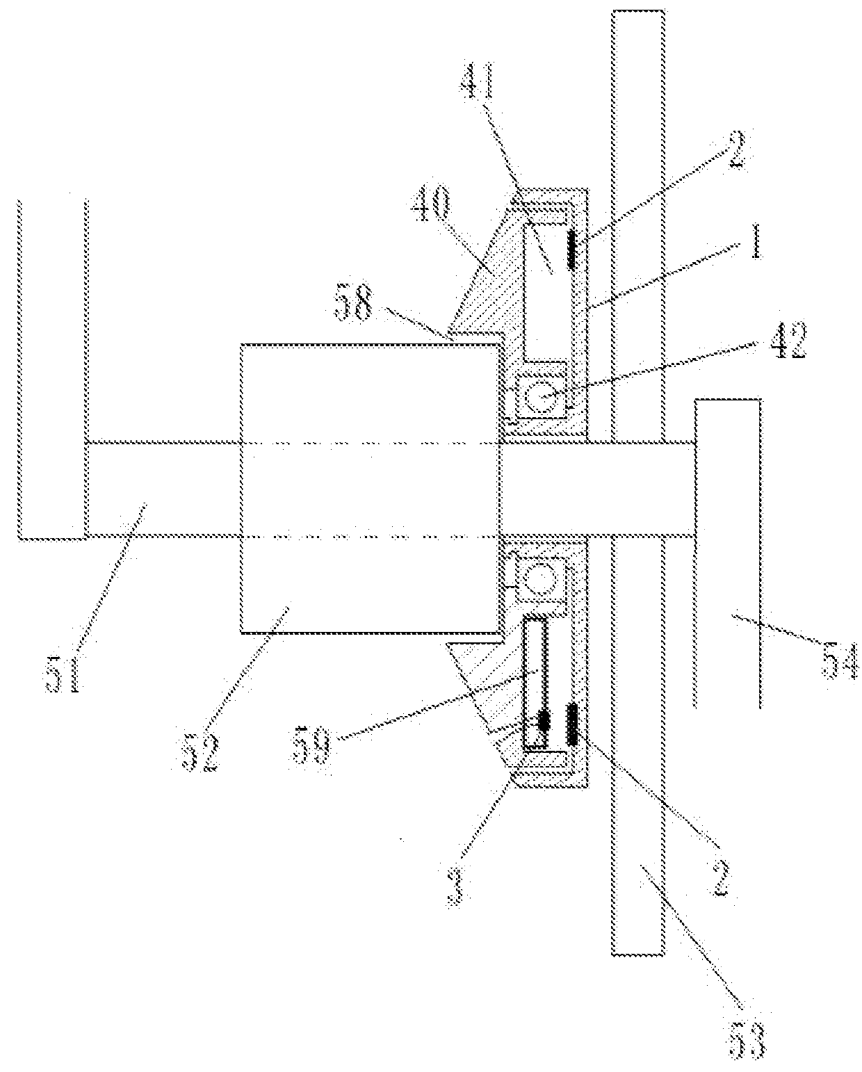
[0126]Power-assistance bicycle using a sensor having multiple magnet blocks evenly distributed in housing. Referring to FIGS. 1, 3, 4 and 6 of the drawings, the sensor is provided on a medial shaft 51 of a conventional electric bicycle. A signal output line of the sensor is connected with a motor controller 29 of the electric bicycle, so as to obtain the power-assistance bicycle of the present invention.

[0127]Parts and structures of the electric bicycle related to installation of the sensor are as follows.

[0128]A power-assistance bicycle using a sensor having multiple magnet blocks evenly distributed in a housing comprises: an electric bicycle and a sensor;

[0129]wherein the electric bicycle has a medial shaft 51, a casing 52 is sleeved on a middle section of the medial shaft 51, the medial shaft 51 is rotationally connected with the casing 52;

[0130]a chain wheel 53 is fixed on the medial shaft 51, and two pedals 54 are respectively fixed on two ends of the medial shaft 51;

[0131]a ba...

embodiment 2

[0152]Power-assistance bicycle using high density sensor with magnetic blocks evenly distributed in housing

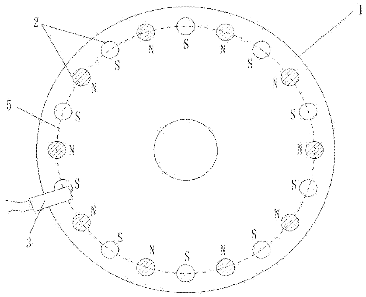
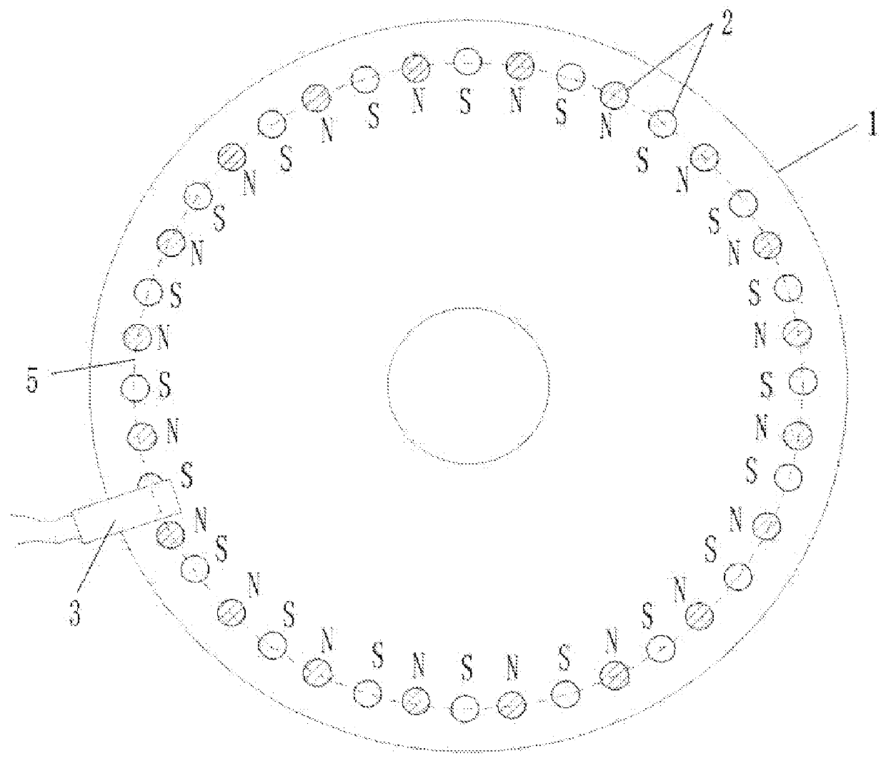
[0153]Referring to FIGS. 2, 3, 4 and 6, of the drawings, a diameter of the annular-groove rotating disk 1 in the hollow ring 41 is 10.0 cm. Forty permanent magnetic blocks 2, each of which has a diameter of 0.6 cm and a magnetic flux of 146˜279(B·H)max / KJ·m−3, are provided on the annular-groove rotating disk 1. The Hall element 3 keeps a 0.2 cm-distance from each permanent magnetic block 2 in a moving state, in such a manner that when the permanent magnetic block 2 passes by, the Hall element 3 generates and outputs a corresponding rectangle wave electrical signal. Other structures of the annular-groove rotating disk 1, the permanent magnetic blocks 2 and the Hall elements 3 are the same with those of the embodiment 1.

embodiment 3

[0154]Power-assistance bicycle using sensor with magnetic blocks evenly distributed in housing with specific circuits

[0155]Referring to FIGS. 1, 3, 5 and 6 of the drawings, the sensor according to the embodiment comprises a sensing element, a power assistance model processor 21, a digital-to-analog converter 27, and an operational amplifier 28 connected in sequence, which is identical to the preferred embodiment 1.

[0156][1] In the sensing element, the Hall element 3 is UGN3075; other elements and element structures are the same with that of the embodiment 1.

[0157][2] The power assistance model processor 21 is a single chip microcomputer 31, and the single chip microcomputer 31 is AT89S52, which means that the AT89S52 single chip microcomputer 31 completes functions of the analog-digital conversion and rate calculator 24, the power assistance model storage 25, and the power assistance model calculator 26.

[0158][3] The digital-to-analog converter 27 is ADC-C8E.

[0159][4] The operationa...


PUM


Abstract

A power-assistance bicycle using a sensor having multiple magnet blocks evenly distributed in a housing, related to electric power-assistance bicycles that provide a power-assistance signal with multipoint magnetic induction. The sensor comprises: a sensing element, a power-assisted model processor, a digital-to-analog converter and an operational amplifier. The sensing element comprises a rotating disk and an annular-groove fixing disk fitted with each other, and a permanent magnetic block and the Hall element are provided in a cavity of the rotating disk and the annular-groove fixing disk. A plurality of permanent magnetic blocks that are opposite in adjacent magnetic polarities are fixedly provided on the rotating disk. The Hall element is provided on the fixing disk and in proximity to the permanent magnetic blocks. The sensor is sleeved on an exterior of a medial axis. The operational amplifier is connected with the motor controller.

Description

CROSS REFERENCE OF RELATED APPLICATION[0001]This is a U.S. National Stage under 35 U.S.C 371 of the International Application PCT / CN2013 / 076810, filed Jun. 5, 2013, which claims priority under 35 U.S.C. 119(a-d) to CN 201210263521.7, filed Jul. 28, 2012.BACKGROUND OF THE PRESENT INVENTION[0002]1. Field of Invention[0003]The present invention relates to the field of a power-assist bicycle, and more particularly to an electric power-assist bicycle for providing a power-assist signal by performing multi-point magnetic induction on a rotating component.[0004]2. Description of Related Arts[0005]A Chinese patent application having an application number of CN 201020295192.0 by Yebao automotive materials Industry Co. Ltd disclosed a power assistance bicycle dedicated sensing device which is cooperated by a magnetic part and a flexible assembly and capable of sensing torque. After a long time utilization, changes of spring constants of the flexible assembly lead to changes of control effects...

Claims


Application Information

Patent Timeline
Patent Type & Authority Patents(United States)
IPC IPC(8): B62M6/50B62M6/65B62M6/55H03M1/12G01D5/14G01P3/487G01D5/245B62M6/90H03M1/24
CPCB62M6/50B62M6/55B62M6/65B62M6/90G01D5/142G01D5/2451G01P3/487H03M1/12H03M1/245
Inventor HUANG, QIANG
Owner CHENGDU KUANHE TECH
Why Eureka
Try Eureka