Engineering plastic / inorganic fiber blends as lost circulation materials

a technology of inorganic fiber and lost circulation materials, applied in the direction of sealing/packing, chemistry apparatus and processes, wellbore/well accessories, etc., can solve the problem of difficult control of particle mixture size distribution, and achieve the effect of reducing the loss of fluid circulation

Active Publication Date: 2016-06-14
BOARD OF SUPERVISORS OF LOUISIANA STATE UNIV & AGRI & MECHANICAL COLLEGE
View PDF10 Cites 11 Cited by
  • Summary
  • Abstract
  • Description
  • Claims
  • Application Information

AI Technical Summary

Benefits of technology

[0021]I have discovered a novel method for reducing lost circulation in drilling wells. The method is especially adapted for use in high-pressure, high-temperature wells. The method employs composite materials as lost circulation materials. The composite materials are economical, and they seal fissures and cracks more rapidly, more efficiently, and at higher temperatures and pressures than are typical of most commercially-available lost circulation materials.
[0022]The composites employed in the novel method comprise an engineering thermoplastic polymer and inorganic fibers, preferably fibers made from basalt. It is important that the polymer and fiber are combined into a composite material, and are not just a simple mixture. A “composite” is an engineered, solid-phase material made from two or more constituent materials having significantly different physical or chemical properties, in which the constituents remain separate and distinct on a macroscopic level within the finished, solid-phase structure. Optionally, the composites may also include additional components such as calcium carbonate (regular or precipitated), and blending agents to improve performance characteristics and material handling properties (e.g., rigidity, stability, or lubrication). The composite Engineering Plastic-Inorganic Fiber Blend (EPIFB) material can be made into pellets, flakes, granules, or particulate forms of various sizes (e.g., 10 to 5,000 microns) through extrusion, followed optionally by further grinding of the extruded materials. Different sized EPIFBs can be used to treat different fracture sizes in a formation. The Young's modulus and compression strength of the material can be controlled in a range up to at least about 11.50 GPa (1667.5 KPSI) and at least about 90 MPa (13,050 PSI), respectively. A high modulus allows the composites to deform progressively to accommodate the opening and closing of fractures, and a high strength allows the material / bridges to carry greater pressure. In a preferred embodiment the material comprises various particle size ranges, and is thermally stable up to at least about 500° F. (260° C.). The material can also be thermally stable at even higher temperatures, depending upon which engineering plastic(s) it contains. The composition may optionally be made using plastics having different melting temperatures to suit a variety of different formations. The composites have superior properties over the properties of a simple mixture. Use of a composite material allows one more readily to control the size distribution of the particles than one ordinarily can with mixtures of the individual components. In general the size distribution of particle mixtures is harder to control unless special efforts are taken with material handling (at increased expense).
[0025]The inorganic component of the lost circulation composite may, for example, be selected from the group consisting of fibers or particles from basalt, glass, calcium carbonate, ceramics, and their respective composites. The inorganic fiber should have a high melting temperature, one that is substantially above the temperature of the formation(s) in which the material will be deployed. It should have high acid solubility, to make it easier to remove the bridge material after drilling with a mild acid. Optionally, but less preferred, the inorganic material can be in the form of particles other than fibers. Basalt fibers are preferred. The fibers supply rigidity, strength, and stiffness to the composite. The inorganic fibers may comprise from 10-70% of the total composite based on weight.
[0026]The composite may optionally comprise one or more additional components such as non-fibrous basalt, calcium carbonate, mica, talc, ceramics, and mixtures thereof, preferably in particulate form (although fibrous forms may also be used). The primary function of these additional components is to supply additional strength and stiffness to the composition. They can also help lower the cost of the composition. Further, these components can increase the density of the material so that the composition will settle more easily in water. Calcium carbonate is a preferred additive for these purposes. Calcium carbonate is available from many sources. An economical source of calcium carbonate is precipitated calcium carbonate (PCC) from sugar mills or sugar refineries. The PCCs of sugar origin, commonly known as lime scum or carbonate slurry, are inorganic precipitates resulting from the purification of beet juice or cane juice by liming and subsequent carbonatation. The PCCs of sugar origin typically have a powdery appearance with grayish hues. They readily agglomerate into lumps. PCCs are generated in enormous quantities as a byproduct of the sugar industry; currently PCC is used as a filling material for gravel mines, waste heaps, and the like; and in some cases it has been used for the correction of soils with excessively clay-like textures or to raise the soil pH. The PCC particle size typically varies from about 1 to about 3000 microns, although the size is not critical. The calcium carbonate or other mineral additive(s) may comprise from about 0% to about 30% of the total lost circulation material by weight.
[0033]Optionally the method may be used to reduce the lost circulation of fluids other than drilling fluids, for example cement fluids during a cementing operation.

Problems solved by technology

In general the size distribution of particle mixtures is harder to control unless special efforts are taken with material handling (at increased expense).

Method used


Image

  • Engineering plastic / inorganic fiber blends as lost circulation materials
  • Engineering plastic / inorganic fiber blends as lost circulation materials

Examples


example 1

Engineering Plastic-Inorganic Fiber Blend (EPIFB) Formulation

[0035]Five example engineering plastic-inorganic fiber blends (EPIFBs) are shown in Table 1. EPIFB 1 through EPIFB 5 were created using recycled polybutylene terephthalate (PET), fine basalt fibers (BF), and precipitated calcium carbonate (PCC) in a one-step extrusion process. During extrusion, the PET was fed upstream, and BFs were side-fed through a side-stuffer. For mixtures that included PCC, the PCC was tumble-mixed first, and the PCC was added along with the PET. The components were melt-blended and extruded in a co-rotating twin screw extruder (Micro 27—Leistritz Corporation, Allendale, N.J., USA) with a screw length / diameter ratio of 40:1. The extrusion temperature profile was 150, 190, 240, 240, 270, 270, 270, 250, 250, and 250° C. from the hopper to a strand die with two 3-mm strand openings, at a fixed 150 rpm screw rotating speed. The extrudate strands were drawn by a pelletizer, and cooled in a cold water bath...

example 2

Characterization of Basic Properties of EPIFBs

[0037]A portion of the extruded hot strands was collected on an aluminum plate immediately following extrusion. The material was hot-pressed to make two 4×4×0.2-inch thick plates (1 inch=2.54 cm), from which test samples were machined to measure blend properties. The blend density was determined by measuring size and weight of machined 1×1×0.2-inch samples. Flexural properties of the composite samples were measured according to ASTM D790-03 using an INSTRON 5582 Testing Machine (Instron Co., Grove City, Pa., USA). Compression strength at the 8% compression strain level was measured for each blend using the INSTRON 5582. TABLE 1 lists selected properties for various blends as shown. The tested blends had a density up to 2.12 g / cm3, an elastic modulus up to 11.3 GPA (1,630,000 PSI), and a compression strength up to 89.55 MPa (12,985 PSI).

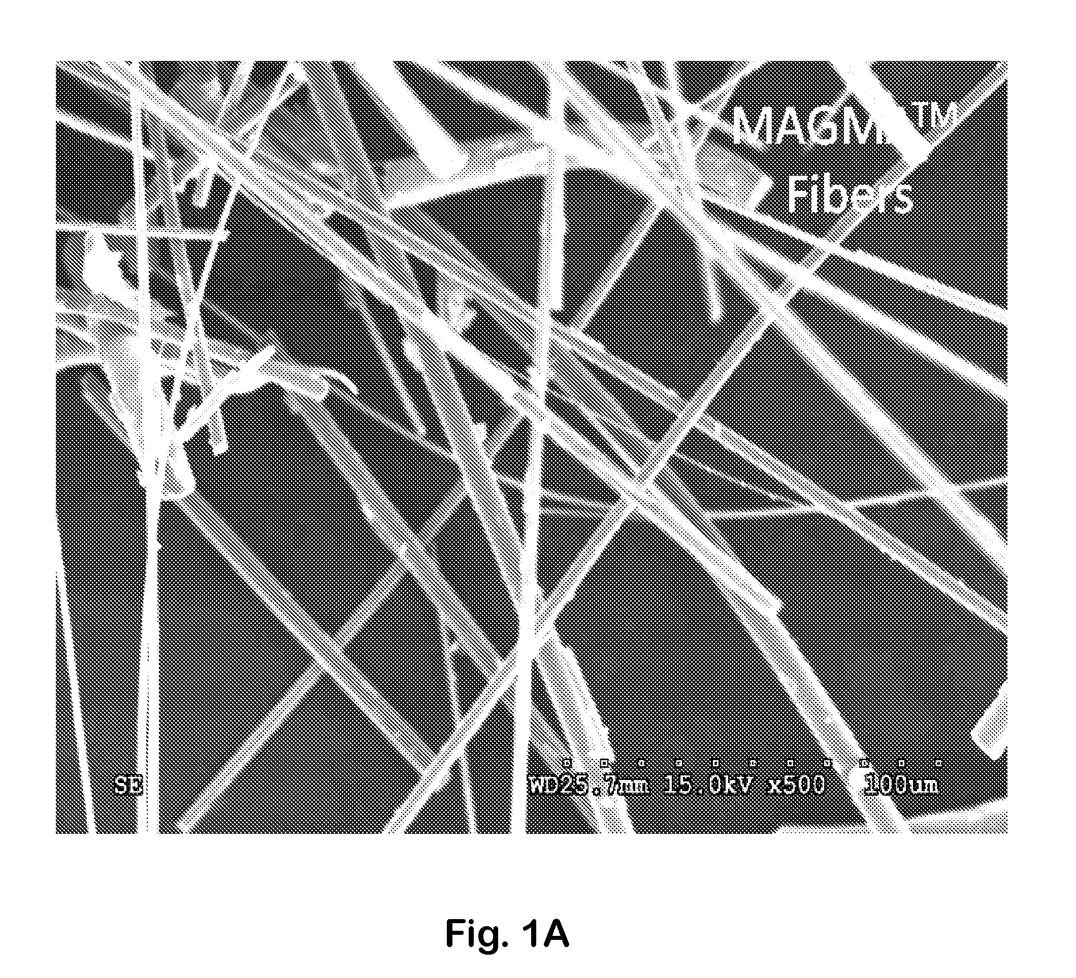
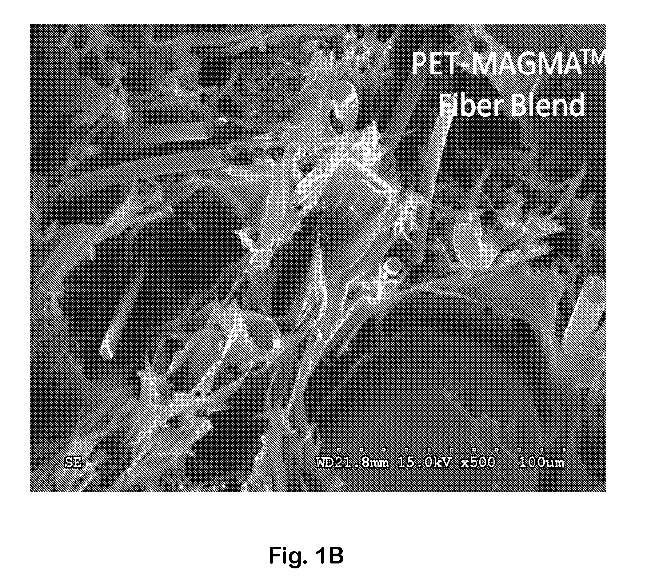
[0038]Composite morphologies were imaged with a Quanta 3D FEG Dual Beam Scanning Electron Microscope (S...

example 3

Particle Size Distribution

[0041]Extruded EPIFB materials from EPIFB4 and EPIFB5 were granulated with a small industrial granulator using a USA standard 8-mesh screen. The material was then screened using USA standard testing sieves (4, 6, 8, 12, 16, 20, 40, 60, 100, and 200 mesh). The sieves were assembled with smaller mesh number screens (i.e., coarser sizes) on top. A sample of 400 g was screened each time. After screening, the material retained on each screen was collected and weighed to the nearest 0.01 gram using an analytical balance. The particle size distribution (PSD) was determined from the measured weight data. The PSD data for EPIFB4 and EPIFB5 are listed in Table 3.

[0042]

TABLE 3Particle Particle Size DistributionParticle Size DistributionSizeGranulated with a 8-meshRecombined with DifferentCategoryScreenParticlesMeshμmPSD-EPIFB4PSD-EPIFB5PSD-S1PSD-S2PSD-S320074000.5001001498.59.923.350.8606025018.524.9217.352.671.34042051.755.9240.3510.95.32084080.780.6270.636.0318.5516...


PUM

PropertyMeasurementUnit
temperatureaaaaaaaaaa
pressuresaaaaaaaaaa
diameteraaaaaaaaaa

Abstract

A method for reducing lost circulation in drilling wells employs composite materials containing an engineering thermoplastic polymer and mineral fibers. Optionally the composites may also include other components such as calcium carbonate and blending agents.

Description

[0001]This is the United States national stage of international application PCT / US2013 / 022847, international filing date Jan. 24, 2013, which claims the benefit of the Feb. 2, 2012 filing date of U.S. provisional patent application Ser. No. 61 / 593,999 under 35 U.S.C. §119(e).[0002]This invention was made with government support under grant number 68-3A75-6-508 awarded by the United States Department of Agriculture. The United States Government has certain rights in the invention.TECHNICAL FIELD[0003]This invention pertains to lost circulation materials, particularly to methods that employ lost circulation materials comprising engineering plastic and inorganic fiber blend composites.BACKGROUND ART[0004]Worldwide demand for energy continues to increase. The search for petroleum is reaching greater extremes for well depths, pressures, and temperatures. High-pressure, high-temperature (HPHT) drilling techniques are often used today. HPHT wells are often classified into three temperature...

Claims


Application Information

Patent Timeline
Patent Type & Authority Patents(United States)
IPC IPC(8): E21B21/00E21B33/138C09K8/487C09K8/504C09K8/508
CPCC09K8/487C09K8/5045C09K8/508E21B21/00C09K2208/08
Inventor WU, QINGLIN
Owner BOARD OF SUPERVISORS OF LOUISIANA STATE UNIV & AGRI & MECHANICAL COLLEGE
Why Eureka
Try Eureka