Process for production of a silica-supported alkali metal catalyst

a technology of alkali metal catalyst and silica supports, which is applied in the direction of catalyst regeneration/reactivation, physical/chemical process catalyst, instruments, etc., can solve the problems of excessive coke formation at the front face of the catalyst bed, the loss of catalyst activity, etc., and achieve the effect of restoring catalyst activity

Active Publication Date: 2016-11-29
MITSUBISHI CHEM UK LTD
View PDF11 Cites 1 Cited by
  • Summary
  • Abstract
  • Description
  • Claims
  • Application Information

AI Technical Summary

Benefits of technology

[0008]Surprisingly, a process has been found which restores catalyst activity to original levels without surface area treatment or damage to the catalyst support.

Problems solved by technology

However, in continuous industrial applications, the catalytic metal component and catalytic surface area are slowly depleted over time causing consequential loss of catalyst activity.
This technique has the disadvantage of poor distribution of the caesium on the catalyst and excessive coke formation at the front face of the catalyst bed.

Method used


Image

  • Process for production of a silica-supported alkali metal catalyst
  • Process for production of a silica-supported alkali metal catalyst
  • Process for production of a silica-supported alkali metal catalyst

Examples


working examples

Caesium Regeneration of an Exhausted Catalyst

[0061]Used Catalyst

[0062]In all examples, samples from the same batch of used and depleted caesium on silica / zirconia catalyst beads (5.05 wt % Cs, 0.86 wt % Zr, 130 m2 / g) were used. This catalyst, when fresh, had 6.7 wt % Cs on it with 0.86 wt % Zr and had a surface area of 327 m2 / g. pH measurements, where quoted, were made by adding an equal volume of water to a sample of solution and observing the colour change in a pH paper immersed in it.

example 1

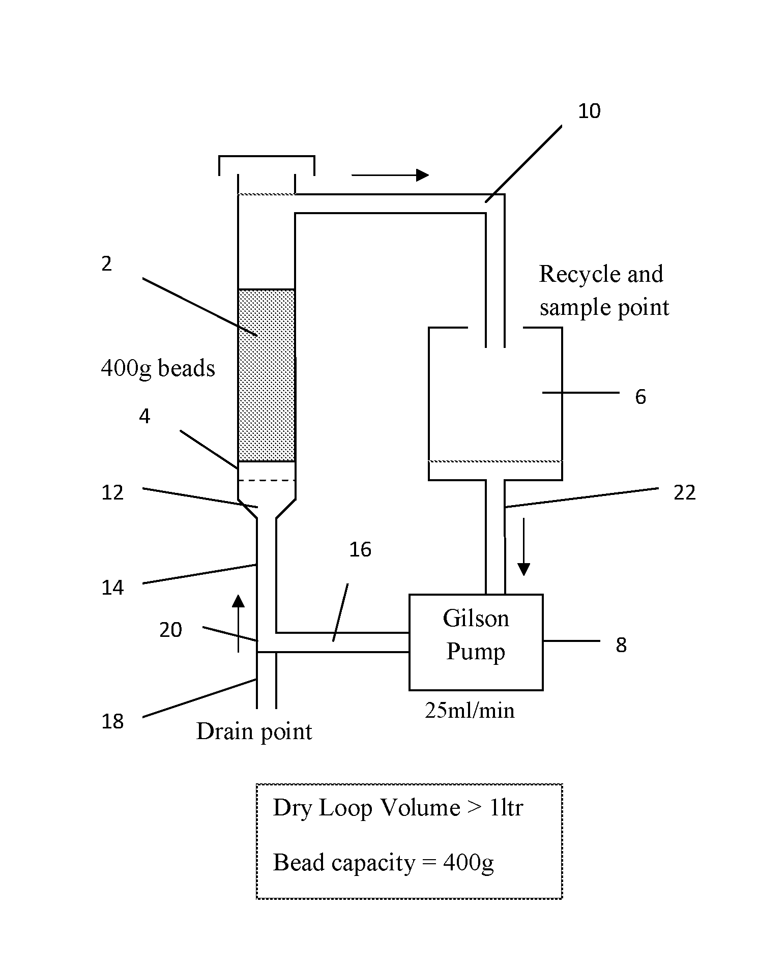
[0063]A 1.2 wt % solution of caesium in methanol was prepared using caesium carbonate (Cs2CO3, 99% Reagent Plus from Aldrich) and dry methanol (2 with a glass frit 4 at the bottom. 1000 ml of caesium solution in methanol was charged to a 2 liter flask 6 (catalyst: solution ratio φ=0.4 kg / liter) and pumped up-flow at 25 ml / min through the catalyst bed from the bottom of the column by a Gilson pump 8. Solution that had passed through the bed was returned to the flask via a recycling conduit 10 in the column 2 above the level of the catalyst. XRF analysis (Oxford Instruments X-Supreme8000) was used to measure the caesium content in solution for the starting feed and periodic samples of the return flow from the column. The solution was recirculated in this way until XRF analysis showed that a steady-state caesium concentration in solution had been reached, which occurred after 2 hrs, when it was measured at 0.55 wt % (54.1% uptake from solution)

[0064]The methanol solution was then drain...

example 2

[0065]The remaining caesium in methanol solution from Example 1 (0.55 wt % Cs, 650 ml) was made up to 1000 ml with fresh methanol and extra caesium carbonate added to increase the concentration of caesium in solution to 1.38 wt %. A fresh 400 g of used catalyst was then regenerated using the same method as Example 1 to yield, after drying, a catalyst with 6.78 wt % caesium on it. The remaining solution contained 0.79 wt % caesium by XRF (42.4% uptake from solution).


PUM

PropertyMeasurementUnit
diameteraaaaaaaaaa
diametersaaaaaaaaaa
wt %aaaaaaaaaa

Abstract

A process for regenerating a silica-supported depleted alkali metal catalyst is described. The level of alkali metal on the depleted catalyst is at least 0.5 mol % and the silica support is a zero-gel. The process comprises the steps of contacting the silica supported depleted alkali metal catalyst with a solution of a salt of the alkali metal in a solvent system that has a polar organic solvent as the majority component. A re-impregnated catalyst prepared by the process of the invention any comprising a silica zero-gel support and a catalytic metal selected from an alkali metal in the range 0.5-5 mol % on the catalyst, wherein the surface area of the silica support is <180 m2/g is also described. The invention is applicable to a process for preparing an ethylenically unsaturated acid or ester comprising contacting an alkanoic acid or ester of the formula R1—CH2—COOR3, with formaldehyde or a suitable source of formaldehyde.

Description

CROSS-REFERENCE TO RELATED APPLICATION[0001]This 35 U.S.C. §371 U.S. National Stage filing claims priority to PCT / GB2013 / 052549 filed Oct. 1, 2013, which claims priority to GB Application No. 1217541.0 filed on Oct. 1, 2012, the contents each of which are incorporated by reference herein.TECHNICAL FIELD AND BACKGROUND[0002]The present invention relates to the production of alkali metal catalysts on silica supports, particularly the regeneration of alkali metal depleted catalysts.[0003]Alkali metal catalysts on silica supports are known to be useful in catalysing various chemical processes. For instance, the alkali metal caesium catalyses the aldol condensation of formaldehyde with alkyl esters or acids to produce ethylenically unsaturated esters or acids, in particular with methyl propionate to form methyl methacrylate (MMA) and methacrylic acid (MA). However, in continuous industrial applications, the catalytic metal component and catalytic surface area are slowly depleted over tim...

Claims


Application Information

Patent Timeline
Patent Type & Authority Patents(United States)
IPC IPC(8): B01J23/92B01J23/04B01J38/64B01J38/48C07C51/353G06F11/36
CPCB01J23/92B01J23/04B01J38/485B01J38/64C07C51/353G06F11/3632G06F11/3656C07C57/04Y02P20/584B01J21/08C07C51/347B01J35/0006B01J35/0013B01J35/1019
Inventor YORK, IAN ANDREWMORRIS, TREVOR HUW
Owner MITSUBISHI CHEM UK LTD
Why Eureka
Try Eureka