Polymers, their preparation and uses

a polymer and polymer technology, applied in the field of organic electroluminescent devices, can solve the problems of low light intensity, poor performance and relatively short lifetime of blue emissive materials known to date, and achieve the effects of reducing the quantity of pfb, avoiding the possibility of phase separation in blends, and improving the lifetime of polymers

Inactive Publication Date: 2017-02-21
CAMBRIDGE DISPLAY TECH LTD
View PDF26 Cites 0 Cited by
  • Summary
  • Abstract
  • Description
  • Claims
  • Application Information

AI Technical Summary

Benefits of technology

[0007]In one approach, the lifetime of the emissive material may be extended by optimisation of the OLED architecture; for example lifetime of the blue material may in part be dependant on the cathode being used. However, the advantage of selecting a cathode that improves blue lifetime may be offset by disadvantageous effects of the cathode on performance of red and green materials. For example, Synthetic Metals 111-112 (2000), 125-128 discloses a full color display wherein the cathode is LiF / Ca / Al. The present inventors have found that this cathode is particularly efficacious with respect to the blue emissive material but which shows poor performance with respect to green and, especially, red emitters.
[0008]Another approach is development of novel blue electroluminescent materials. For example, WO 00 / 55927, which is a development of WO 99 / 48160, discloses a blue electroluminescent polymer of formula (a):
[0010]In essence, the separate polymers disclosed in WO 99 / 48160 are combined into a single molecule. The F8 repeat unit is provided for the purpose of electron injection; the TFB unit is provided for the purpose of hole transport; and the PFB repeat unit is provided as the emissive unit. The combination of units into a single polymer may be preferable to a blend, for example intramolecular charge transport may be preferable to intermolecular charge transport, potential difficulties of phase separation in blends is avoided.
[0011]WO 02 / 92723 and WO 02 / 92724 disclose replacement of some of the F8 repeat units in the polymer illustrated above with 9,9-diarylfluorene repeat units which has surprisingly been found to improve lifetime of the polymer.
[0012]WO 99 / 54385 and EP 1229063 disclose copolymers of fluorenes and PFB-type triarylamine repeat units. EP 1229063 discloses a copolymer of F8:TFB in a 70:30 ratio. It is an object of the present invention to provide long lived blue electroluminescent polymers, in particular blue electroluminescent polymers that are suitable for use in a full colour electroluminescent display.GENERAL DESCRIPTION OF THE INVENTION
[0013]The present inventors have surprisingly found that reduction in the quantity of PFB leads to improved efficiency in certain device architectures, in particular for full color displays. Furthermore, the present inventors have surprisingly found that it is unnecessary to have separate hole transporting units and blue emissive units; it has been found that both functions may be performed by the PFB unit. Surprisingly, the omission of TFB from the prior art polymers described above is found to result in a significant improvement in lifetime.

Problems solved by technology

One drawback with existing polymer OLED displays relevant to this development is the relatively short lifetime of blue emissive materials known to date (by “lifetime” is meant the time for the brightness of the OLED to halve at constant current when operated under DC drive).
However, the advantage of selecting a cathode that improves blue lifetime may be offset by disadvantageous effects of the cathode on performance of red and green materials.
The present inventors have found that this cathode is particularly efficacious with respect to the blue emissive material but which shows poor performance with respect to green and, especially, red emitters.

Method used


Image

  • Polymers, their preparation and uses
  • Polymers, their preparation and uses
  • Polymers, their preparation and uses

Examples


examples

Monomer Examples

[0045]Monomers according to the invention were prepared in accordance with the scheme below:

[0046]

Monomer Example M1

2,7-dibromo-9,9-diphenylfluorene

2,7-Dibromofluorenone

[0047]

[0048]In a 3 L flange flask fluorencone (100.006 g, 0.555 mol), phosphorus pentoxide (110.148 g, 0.776 mol) and trimethylphosphate (1200 mL) were mixed. Under mechanical stirring, a solution of bromine (63 mL, 1.23 mol) in trimethylphosphate (200 mL) was quickly added. This clear solution was then heated for 22 hours at 120° C. The mixture was allowed to cool to room temperature, then poured into 3 L of water. When sodium thiosulfate was added (50.045 g) the mixture turned yellow. Stirring was maintained for 1 hour then the yellow solid was filtered. This solid was heated in methanol to remove the mono-brominated compound and gave 176.183 g (98% pure by HPLC, 94% yield).

[0049]1H NMR (CDCl3) 7.73 (2H, d, J 2.0), 7.61 (2H, dd, J 7.6, 2.0), 7.36 (2H, d, J 8.0) 13C NMR (CDCl3) 142.3, 137.5, 135.3, 1...

polymer example p1

[0062]A blue electroluminescent polymer according to the invention was prepared in accordance with the process of WO 00 / 53656 by reaction of 9,9-di-n-ooctylfluorene-2,7-di (ethylenylboronate) (0.65 equivalents), 2,7-dibromo-9,9-diphenylfluorene (0.30 equivalents) and N,N′-di(4-bromophenyl)-N,N′-di(4-n-butylphenyl)-1,4-diaminobenzene (0.05 equivalents) to give polymer P1:

[0063]

Device Example

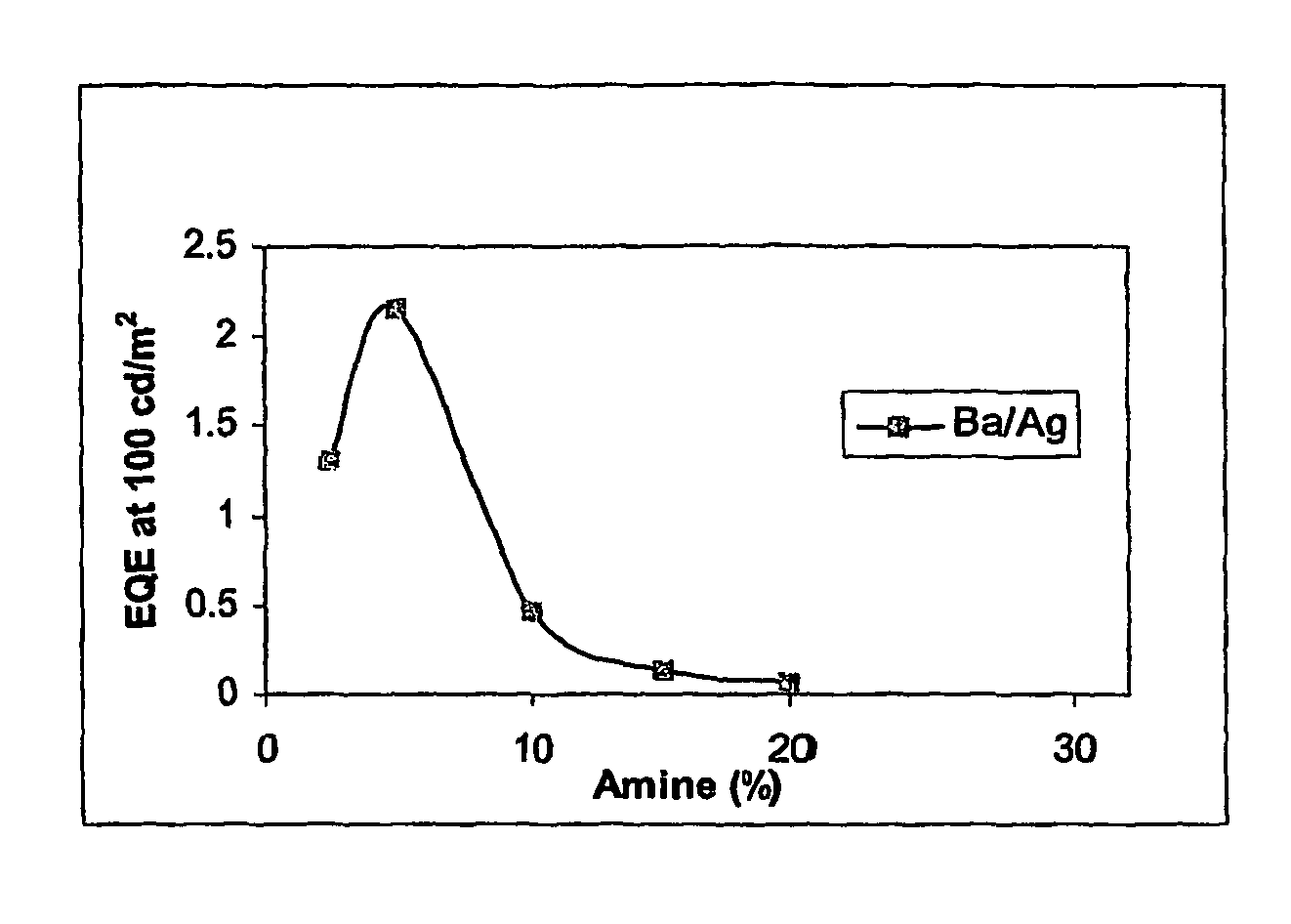
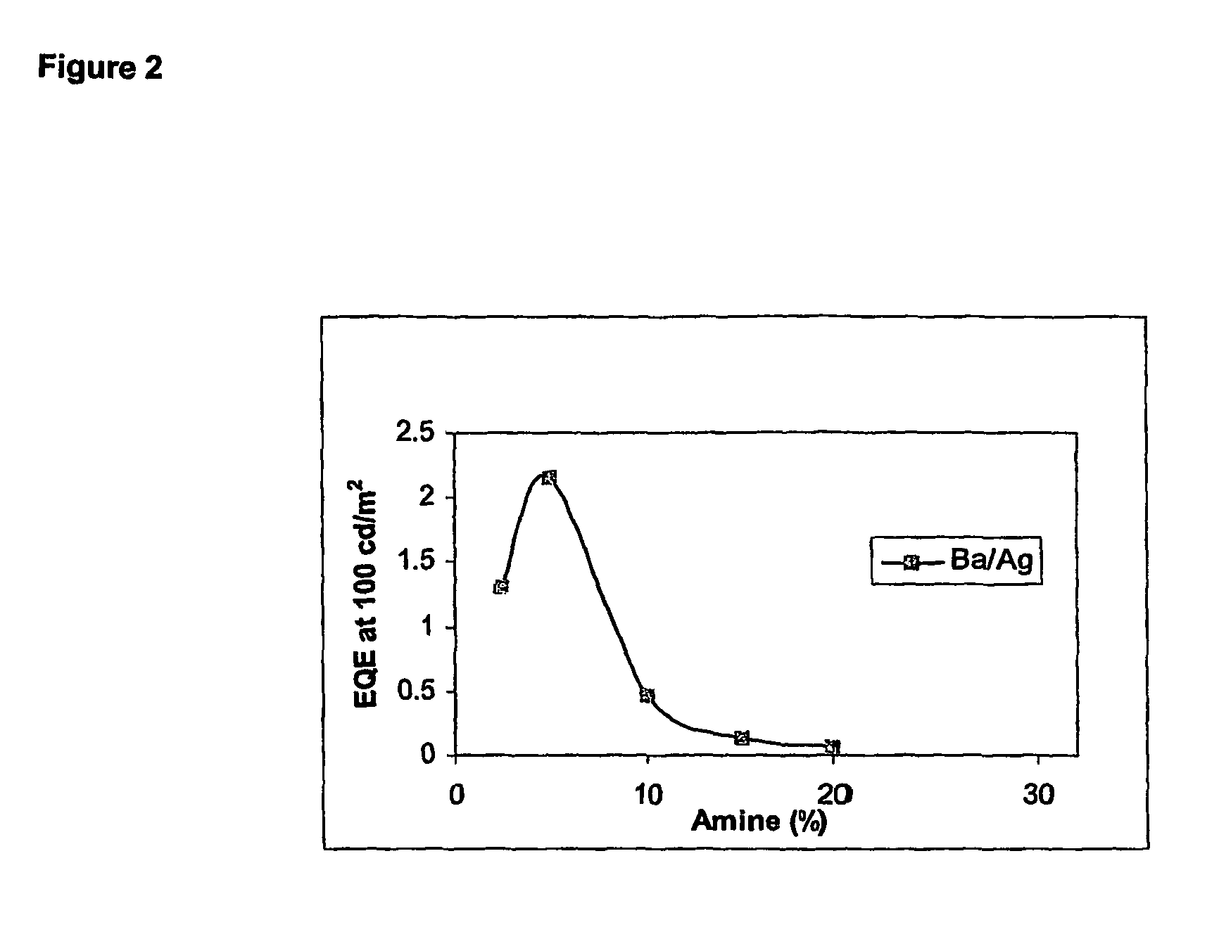
[0064]Onto indium tin oxide supported on a glass substrate (available from Applied Films, Colorado, USA) was deposited a layer of PEDT / PSS, available from Bayer® as Baytron P® by spin coating. A layer of polymer P1 was deposited over the PEDT / PSS layer by spin-coating from xylene solution. Onto the polymer P1 was deposited by evaporation a cathode consisting of a first layer of barium and a second, capping layer of silver.

[0065]For the purpose of comparison, identical devices were prepared except that molar ratio of PFB repeat units was varied. As can be seen, lifetime at amine contents of 10% or ...


PUM

PropertyMeasurementUnit
wavelength rangeaaaaaaaaaa
mol %aaaaaaaaaa

Abstract

A polymer comprising a first repeat unit of formula (I), wherein each Ar is independently selected from optionally substituted aryl or heteroaryl and the group of formula (I) is present in a molar ratio of less than or equal to 10%, and, optionally, a second, optionally substituted repeat unit having a single nitrogen atom in its backbone of formula —Ar—N(Ar)—Ar— in a molar ratio of no greater than 5%.

Description

FIELD OF THE INVENTION[0001]The invention relates to materials for optical devices, in particular organic electroluminescent devices, and the control of their physical and electronic properties.BACKGROUND OF THE INVENTION[0002]One class of opto-electrical devices is that using an organic material for light emission or detection. The basic structure of these devices is a light emissive organic layer, for instance a film of a poly (p-phenylenevinylene) (“PPV”) or polyfluorene, sandwiched between a cathode for injecting negative charge carriers (electrons) and an anode for injecting positive charge carriers (holes) into the organic layer. The electrons and holes combine in the organic layer generating photons. In WO 90 / 13148 the organic light-emissive material is a polymer. In U.S. Pat. No. 4,539,507 the organic light-emissive material is of the class known as small molecule materials, such as (8-hydroxyquinoline) aluminium (“Alq3”). In a practical device one of the electrodes is trans...

Claims


Application Information

Patent Timeline
Patent Type & Authority Patents(United States)
IPC IPC(8): C09K11/06C08G73/02C08G61/02H05B33/14H01L51/00H01L51/30
CPCC08G73/026C08G61/02C09K11/06H01L51/0043H05B33/14C09K2211/1416C09K2211/1433H01L51/0035H01L51/0039H01L51/0059H10K85/111H10K85/115H10K85/151H10K85/631C08G61/12C08G61/10C08G73/00
Inventor TIERNEY, BRIANGRIZZI, ILARIAFODEN, CLAREPATEL, NALINLEADBEATER, MARK
Owner CAMBRIDGE DISPLAY TECH LTD
Why Eureka
Try Eureka