
Optimised energy storage device having capacitor material on lead based negative electrode

a technology of negative electrode and capacitor material, which is applied in the manufacture of cell components, batteries, and final products, etc., can solve the problems of lead-acid batteries failing prematurely, forming a layer of lead sulphate on the surface, and battery use in these vehicles still suffers from a number of problems, so as to reduce the electrical resistance of the electrode, enhance mechanical strength, and increase the effect of weigh

Active Publication Date: 2017-05-30
COMMONWEALTH SCI & IND RES ORG +1
View PDF445 Cites 23 Cited by
  • Summary
  • Abstract
  • Description
  • Claims
  • Application Information

AI Technical Summary

Benefits of technology

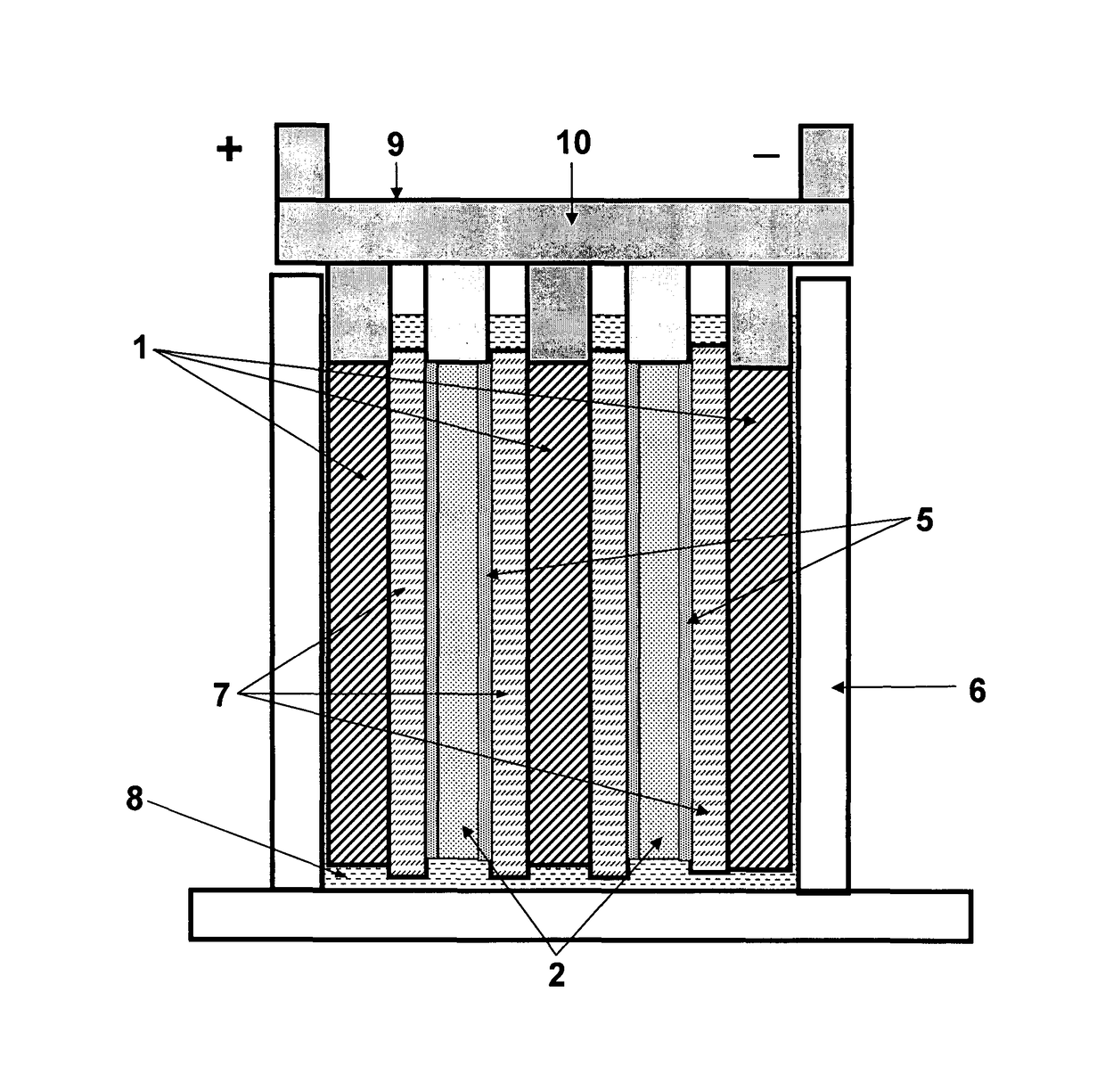
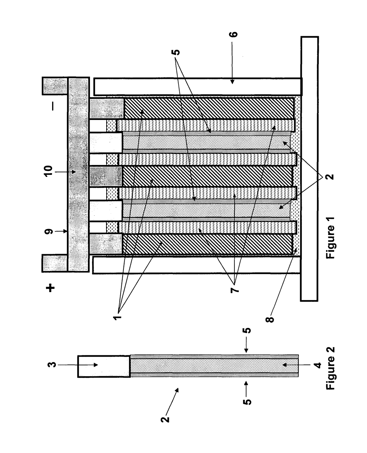
[0020]It has been found that the layer-configuration provides the optimal working of the battery, particularly with the amounts of carbonaceous materials in the capacitor material described above. Moreover, it has been found that the capacitor material of each negative electrode should constitute between 1 and 15% by weight of the negative battery electrode material. Below 1% is insufficient for minimum performance requirements of the device. Above 10% it has been found that saturation is reached, such that the further weight increase does not further increase performance. Nevertheless, other than cost and weight consideration, an increase in the mass of capacitor material above 10% is acceptable to a level of about 15%.
[0021]It has been found that layer-configuration provides the substantial area of cohesive interface between capacitor material and battery material which is formed through the reaction with lead battery material and carbonaceous capacitor material, resulting in enhanced mechanical strength and reduced electrical resistance of the electrode. Along with these beneficial effects, a greater lead content in the capacitor material is transferred during operation from the battery material directly contacting with capacitor material which controls electrode potential enough to depress gassing.

Problems solved by technology

Whilst there have been many significant advances in the development of new batteries and power networks for vehicles relying at least partly on electric power, the batteries used in these vehicles still suffer from a number of problems.
In the situation where lead-acid batteries are utilized, particularly in hybrid electric vehicles, the high rate of battery discharging and recharging results in the formation of a layer of lead sulphate on the surface of the negative plate, and the generation of hydrogen / oxygen at the negative and positive plates.
This largely arises as a result of high current demands on the battery.
Under simulated HRPSoC duty, such as hybrid electric vehicle operations, the lead-acid batteries fail prematurely mainly due to the progressive accumulation of lead sulphate on the surfaces of the negative plates.
This occurs because the lead sulphate cannot be converted efficiently back to sponge lead during charging either from the regenerative braking or from the engine.
Eventually, this layer of lead sulphate develops to such an extent that the effective surface area of the plate is reduced markedly, and the plate can no longer deliver the higher current demanded from the automobile.
This significantly reduces the potential life span of the battery.

Method used


Image

  • Optimised energy storage device having capacitor material on lead based negative electrode
  • Optimised energy storage device having capacitor material on lead based negative electrode

Examples


example 1 — e1

Example 1—E1

[0076]A monoblock battery (87 mm W×150 mm L×110 mm H) of 6 cells in a VRLA arrangement was constructed with following components, processes and conditions;

[0077]Negative electrode: grid (Pb with 0.1% Ca) of 76 mm W×76 mm H×1.4 mm thickness, 5 plates / cell

[0078]Aqueous mix (density 4.0) of lead oxide, expander, polyester fiber and sulfuric acid was applied to grids, cured, dried and then tank formed according to conventional methods.

[0079]The capacitor mix is composed of

[0080]

Carbon black (furnace black)43 mass partsActive carbon (SSA 2300 m2 / g)38Polyester fiber (20 μm diameter, 5aspect ratio 150)Chloroplane rubber10CMC 4Water280□ based onthe 100 massparts of 100%solids content.

[0081]The mix is applied onto both sides of all formed plates by the doctor blade method and dried. Capacitor mass was 5% of total negative active mass (dry base) with 75% porosity.

[0082]Positive electrode: grid (Pb with 0.035% Ca, 0.007% Ba, 1.8% Sn) of 76 mm W×76 mm H×1.7 mm thickness, 4 plates / ce...

reference example 1

[0094]In place of the negative electrode of Example 1, the negative electrodes were prepared to have a type of reference configuration as follows:[0095]A half area of the negative electrode was pasted with the battery mix, and the other half was pasted with the capacitor mix. The halves were a left-hand side and a right-hand side, coated on both faces with the battery material, or capacitor material, respectively.

reference example 2

[0096]In place of the container used in Example 1, new larger one (87 mmW×220 mmL×110 mmH) was used to insert the following plate group composed of the battery and capacitor portions keeping the same group pressure of 60 kPa. The battery portion was the same to above E1 and capacitor portion was composed of the 5 capacitor negative electrodes and 4 positive electrodes alternatively arranged in series and interleaved with AGM of 0.5 mm thickness. The both electrodes were constructed with 0.6 mm thick lead sheet substrates with 45% punched-openings by coating capacitor and positive battery mixes, respectively and the dry thicknesses of the negative and positive electrodes were about 0.9 and 0.7 mm thick, respectively. The substrates were the same alloys as E-1. The mass of capacitor material was 5% by weight of the battery material. The positive electrode was tank-formed before stacking and assembling.

[0097]All negative and positive electrodes were welded (COS) to be electrically conn...


PUM


Abstract

A lead-acid battery comprising: —at least one negative electrode comprising lead-based battery electrode material and at least one region of capacitor material overlying the lead-based battery electrode material, each electrode being in electrical connection to an outer terminal of the battery, and —at least one positive lead-dioxide based battery electrode, each positive electrode being in electrical connection to a second outer terminal of the battery, —separator interleaving the facing electrodes; —electrolyte filling at least the space of the electrodes and separators wherein the capacitor material overlying the lead-based battery electrode material comprises 20-65% by weight of a high electrical conductivity carbonaceous material, 30-70% of a high specific surface area carbonaceous material, at least 0.1% lead and binder.

Description

[0001]This application is the U.S. national phase of International Application No. PCT / AU2008 / 000405 filed 20 Mar. 2008, which designated the U.S. and claims priority to AU Application No. 2007901466 filed 20 Mar. 2007, the entire contents of each of which are hereby incorporated by reference.BACKGROUND[0002]The present invention relates to energy storage devices, including batteries such as lead-acid batteries.[0003]There is growing demand for the development and introduction of vehicles that do not rely almost entirely on fossil fuels, to combat air pollution in urban environments and to reduce the global consumption of limited supplies of the fossil fuels. Such vehicles fall into three main classes: fuel-cell vehicles (FCVs), electric vehicles (EVs), hybrid electric vehicles (HEVs). There are several types of hybrid electric vehicles, namely, micro-, mild-, medium- and full-hybrid. The battery voltage of the hybrid electric vehicles increases in the order: 12 V in micro hybrid, 3...

Claims


Application Information

Patent Timeline
Patent Type & Authority Patents(United States)
IPC IPC(8): H01M4/14H01M4/62H01M10/06H01M10/12H01M4/02
CPCH01M4/14H01M4/621H01M4/625H01M4/627H01M10/06H01M10/121H01M2004/021Y02E60/10Y02P70/50H01M10/12H01M10/08H01M4/685H01M10/4235H01G11/38H01M2300/0011H01M2220/20H01M50/44H01M50/414H01M12/02Y02T10/70
Inventor LAM, LAN TRIEUFURUKAWA, JUNTAKADA, TOSHIMICHIMONMA, DAISUKEKANOU, TETSUYA
Owner COMMONWEALTH SCI & IND RES ORG
Learn More