Apparatus and process for desalination of water

a technology of desalination apparatus and water, which is applied in the direction of reverse osmosis, multi-stage water/sewage treatment, waste water treatment from quaries, etc., can solve the problems of low water recovery rate of ro systems, main energy consumption of ro technology, and disadvantages of ro technology, so as to reduce processing time, improve productivity, and increase productivity

Active Publication Date: 2017-06-27
SULZER MANAGEMENT AG
View PDF22 Cites 9 Cited by
  • Summary
  • Abstract
  • Description
  • Claims
  • Application Information

AI Technical Summary

Benefits of technology

[0011]The present invention achieves these objects and provides a solution to this problem by means of passing the first byproduct stream in a second desalination step through a suspension crystallization unit to form a second product water stream having a reduced salt concentration relative to that of the first byproduct stream and a second byproduct stream having an increased salt concentration relative to that of the first byproduct stream. As a result, the first byproduct stream of an RO membrane desalination plant having a relatively high salt concentration is readily concentrated further by the suspension crystallization to give a reduced volume of high salinity solution (waste concentrated brine) as the second byproduct stream and a second product water stream having a reduced salt concentration and thus suitable for recycling or other applications. Therefore the overall waste volume is significantly reduced.
[0024]In a preferred embodiment of the process having a third desalination step in the same or a second crystallization unit, the second byproduct stream is passed through a second heat exchanger thereby reducing its temperature prior to passing through the same or second suspension crystallization unit so as to improve productivity and reduce the processing time. In another preferred embodiment of the process having a third desalination step, the temperature of the second byproduct stream is reduced prior to entering the same or second suspension crystallization unit, preferably to a temperature between about 2 to about 20° C., more preferably about 2 to about 10, most preferably about 2 to about 5. Similarly, in yet another preferred embodiment of the process having a third desalination step, the second byproduct stream is crystallized at a temperature between about −4 to about −13° C., preferably about −6 to about −10, more preferably about −7.5 to about −8.5. These temperature ranges for the temperature reduction of the stream and its subsequent crystallization make it possible to obtain the maximum benefit in improved productivity and processing time.

Problems solved by technology

Due to a lack of uniform distribution of fresh water supplies, it is necessary in many regions to obtain fresh water by desalination of a saline solution, for example from the sea.
The main energy consumption in RO technology results from the pressurization of the saline solution.
Nonetheless RO technology has its disadvantages.
Since the pressure required to recover additional fresh water increases as the saline solution or brine stream is concentrated, the water recovery rate of RO systems tends to be low.
A related further major disadvantage is then the cost and environmental impact of disposing of the large volume streams of concentrated saline solution byproduct (first byproduct streams) from the RO plant, particularly for inland RO plants.
Such practices are not environmentally friendly, and thus they are no longer acceptable.
Such thermally-based concentration methods have the disadvantage of being energy intensive and thus costly.
In addition, they are susceptible to scale formation and its associated thermal and mechanical problems.
Alternatively, first byproduct streams may be concentrated by solar ponds having low energy costs, but this thermal method requires large amounts of land and direct sunlight and suffers from low productivity and expensive and time consuming maintenance.
Furthermore solar thermal methods are not applicable to all regions and / or climates in that the presence of dust may block sunlight and / or surface area for evaporation, thereby increasing the time required for evaporation.
In addition, the evaporated water is lost to the environment in the case of a pond, and it is not available then as a supply of drinking water.
Finally toxic compounds such as sulfur-based compounds may evaporate and be transferred to the environment resulting in EHS issues.
Electrodialysis methods suffer the disadvantage though of being sensitive to membrane fouling and scaling, and they also require large quantities of direct current and their electric fields are only capable of removing ionic components.

Method used


Image

  • Apparatus and process for desalination of water
  • Apparatus and process for desalination of water
  • Apparatus and process for desalination of water

Examples


examples

[0079]The following examples are set forth to provide those of ordinary skill in the art with a detailed description of how the processes, apparatuses and uses claimed herein are evaluated, and they are not intended to limit the scope of what the inventors regard as their invention. Unless indicated otherwise, parts are by weight, and temperature is in degrees Celsius (° C.).

[0080]The pilot plant used in the examples had the configuration shown in FIG. 7 and described earlier. The temperature of the heat transfer medium (HTM) was between 15 and −19° C. The temperature of the feed (the first byproduct stream 6′) was 15° C., and the final operating temperature was −19° C.

[0081]The weights of all streams removed from the crystallizer were measured using a digital balance, and freezing point measurements were carried out where appropriate (at lower purities, where deviations from the pure product freezing point are significant enough to be detected). Samples were taken during the test r...

examples 1 to 3

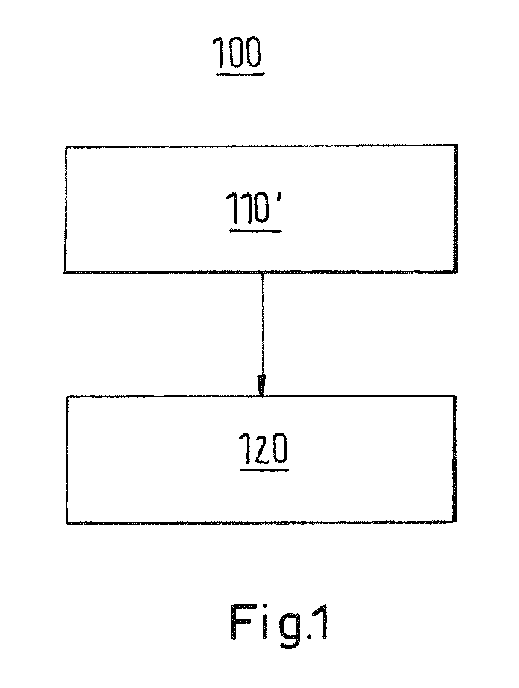
[0087]In these examples, a saline solution feed stream (first byproduct stream 6′) having a salt concentration of from 3.5 to 6.1 weight % was treated in a second desalination step 120 by crystallization in a single stage of the suspension crystallization pilot plant and yielded the results shown in Tables 1 to 3. It is noted that Examples 2 and 3 are both based on computational modeling of the process in the plant. FIG. 9 summarizes the water recovery versus residue temperature obtained in Examples 1 to 3.

[0088]The examples demonstrate that the process and apparatus of the invention may be usefully used in treating the first byproduct stream 6′ (waste effluent streams) of RO membrane desalination plants having a variety of saline solution concentrations. Nonetheless the data in the tables and figure show that it will generally be preferred to have a salt concentration between about 3 and about 7 weight %. In order to have the most economical usage of the RO membrane plant, the salt...

example 4

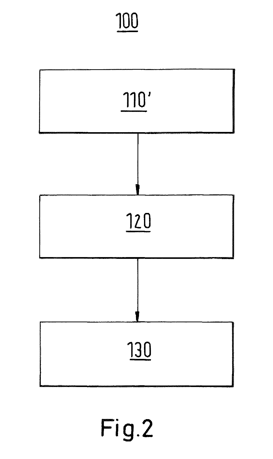
[0090]In this example, a suspension crystallization was carried out as in Example 1, and the residue (second byproduct stream 9) was passed in a third desalination step 130 through a static crystallization unit 10. The pilot plant used in this example consisted of a standard static crystallization unit of a 70 liter crystallizer, equipped with the same type of crystallizer elements as used for industrial crystallizers. It therefore avoids any risk in the design for final capacity as no scale up needs to be done.

[0091]In this example, a sweating stage was incorporated, which results in a higher product purity and higher salt rejection; however, the water recovery and yield are somewhat reduced and larger equipment and a longer processing time is required. One skilled in the art will understand how to make trade-offs in these particular aspects in order to obtain an optimized result for a particular situation and requirements.

[0092]This example demonstrates that the second byproduct s...


PUM

PropertyMeasurementUnit
temperatureaaaaaaaaaa

Abstract

A process for desalinating water is disclosed. The process comprises the steps of passing a feed stream of saline solution 2′ in a first desalination step through a reverse osmosis membrane desalination plant 3′ comprising at least one reverse osmosis desalination unit 4′ to form a first product water stream 5′ having a reduced salt concentration relative to that of the feed stream of saline solution 2′ and a first byproduct stream 6′ having an increased salt concentration relative to that of the feed stream of saline solution 2′ characterized in that the first byproduct stream 6′ is passed in a second desalination step through a suspension crystallization unit 7 to form a second product water stream 8 having a reduced salt concentration relative to that of the first byproduct stream 6′ and a second byproduct stream 9 having an increased salt concentration relative to that of the first byproduct stream 6′. The invention further relates to an apparatus 1 for carrying out said process. The present invention further relates also to the use of the process or apparatus 1 for the reduction of the volume of the first byproduct stream of a reverse osmosis membrane desalination plant 3′, preferably an in-land desalination plant 3′, or in a device or plant or process for producing desalinated water, for salt production, for co-production of power and desalinated water, or for air conditioning.

Description

BACKGROUND OF THE INVENTION[0001]The present invention relates to a process for desalination of saline solution. The present invention also relates to an apparatus for carrying out this process, and the use of said process or apparatus for the reduction of the volume of concentrated saline solution byproduct of a reverse osmosis membrane desalination plant, or in a device or plant or process for producing desalinated water, for salt production, for co-production of power and desalinated water, or for air conditioning.[0002]In the present application, the term “saline solution” refers to any aqueous solution containing at least one dissolved salt, and the term “first byproduct stream” refers to a concentrated saline solution byproduct obtained from a reverse osmosis (RO) membrane desalination plant. Other examples of concentrated saline solutions include seawater, brackish water, or mining water. It is noted that the saline solution feed stream and the first byproduct stream of a RO ...

Claims


Application Information

Patent Timeline
Patent Type & Authority Patents(United States)
IPC IPC(8): C02F1/44B01D61/08C02F1/22B01D61/02C02F1/00C02F101/10C02F103/08C02F103/10
CPCC02F1/441B01D61/08C02F1/22C02F1/008C02F2101/10C02F2103/08C02F2103/10C02F2209/001C02F2209/02C02F2209/05C02F2303/10C02F2303/20C02F2303/22Y02W10/30Y02W10/37Y02A20/131Y02A20/124C02F9/00
Inventor DETTE, SEVERINEAHMAD, MANSOUR M. MSTEPANSKI, MANFRED
Owner SULZER MANAGEMENT AG
Why Eureka
Try Eureka