Particulate materials, composites comprising them, preparation and uses thereof

a technology of composite materials and particles, which is applied in the field of particles and composite materials, can solve the problems of difficult dispersion, formidable obstacle to dispersion, and limited industrial use, and achieves good results

Active Publication Date: 2017-09-19
HAYDALE GRAPHENE IND
View PDF93 Cites 6 Cited by
  • Summary
  • Abstract
  • Description
  • Claims
  • Application Information

AI Technical Summary

Benefits of technology

[0108]After treatment the disaggregated particulate product has been found to exhibit various advantageous properties. One important property is specific surface area, which can be determined by the standard BET or NMR methods. Conventional treatments applied to aggregate CNT particles struggle to achieve BET specific surface areas better than 50 m2 / g in the product material, because of the great tendency to maintain aggregation. We find that CNT granules treated by the present methods can give materials with BET specific surface areas of at least 300, at least 500, at least 800 or at least 1000 m2 / g. These materials are believed to be new per se in the context of bulk production methods, and they are an aspect of the present invention. Methods comprising synthesising CNTs or graphitic particles and then applying the present methods to disaggregate or exfoliate the particle product are a further aspect of the invention. Methods in which the disaggregation or exfoliation treatment is followed by dispersion of the material in a liquid vehicle or matrix material (or matrix material precursor) are a further aspect of the invention. This dispersion may involve the use of one or more dispersants such as surfactants, or polymeric materials whose molecules associate themselves with the individual dispersed component particles e.g. separated CNTs or graphene sheets, to inhibit their re-aggregation in the liquid.

Problems solved by technology

However their industrial uses are still very limited, largely because of processing and handling issues.
The resulting CNTs are usually contaminated with residues of one or more of catalyst, amorphous carbon and (usually undesired) closed fullerenes and these residues tend to bind the CNTs together.
With CNTs this is exacerbated by their very high aspect ratio leading to extensive tangling and winding, and structures such as lumps, granules, tangled bundles or “ropes” of twisted CNTs.
However the routine existence of the bulk product in the form of tangled agglomerates and their lack of relative chemical affinity for the vehicle or matrix presents a formidable obstacle to dispersion.
Where dispersions can be formed these tend to be dispersions of agglomerates, so that the properties of the CNTs themselves are scarcely made available.
This has met with some success, but these techniques for functionalising the particles remain highly inefficient, inconvenient and expensive as far as industrial application is concerned.
Moreover they still achieve only modest levels of de-aggregation of the individual CNTs.
Typically the CNTs are still twisted into ropes, and often have quite severe structural damage to the carbon layers (graphene layers of the CNT wall) as well as shortening of the tubes, with consequent loss of valuable CNT properties.
CNTs also present a real or perceived health hazard if inhaled or in general if they contact permeable body membranes.
Accordingly, despite widespread knowledge of their potential properties and of ways of making them, they have found limited industrial application.
However the known methods are laborious and expensive.
Even more than with CNTs, however, there has been no easy commercial-scale supply of readily-useable graphene material.
Synthetic laboratory-grown graphene is available only in tiny quantities at enormous cost.
A number of important practical applications exist but their implementation is necessarily very limited.

Method used


Image

  • Particulate materials, composites comprising them, preparation and uses thereof
  • Particulate materials, composites comprising them, preparation and uses thereof
  • Particulate materials, composites comprising them, preparation and uses thereof

Examples


second apparatus embodiment

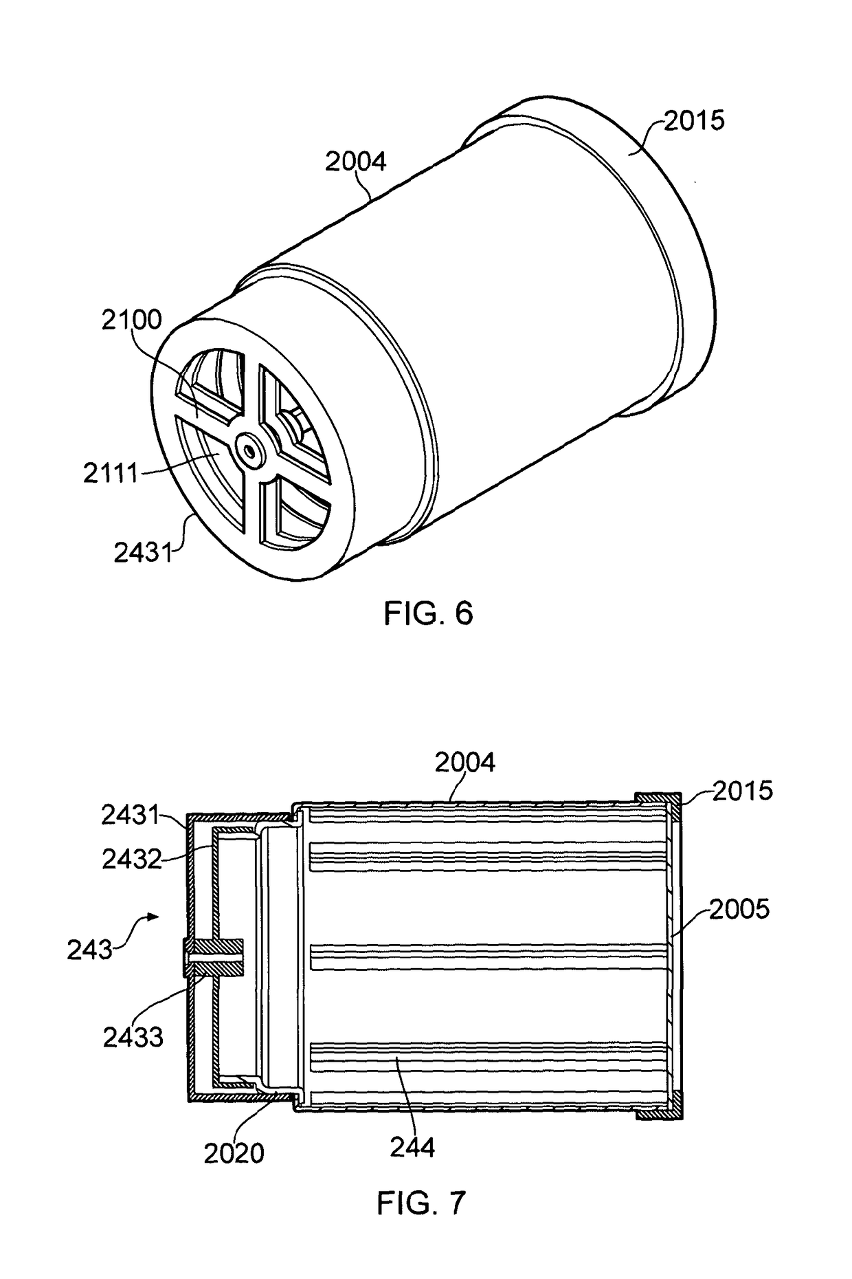
[0145]FIGS. 6 and 7 show a further treatment drum suitable for treatment of particles comprising CNTs, or graphitic granules. It has a cylindrical drum wall 2004 of metal e.g. steel or aluminium to act as counter-electrode. It is to be mounted for rotation in a vacuum chamber, e.g. on support rollers.

[0146]The end walls are insulative. A rear end wall is of glass or inert plastics e.g. PTFE and comprises inner and outer layers 2432,2431 between which a filter layer (not shown) is clamped. This end wall filter module has large windows 2111 occupying more than half its area so that gas flow speed through the filter is low. This is found to improve plasma stability i.e. inhibit arcing. The centre of the rear end wall has a holder for the axial electrode, not shown. The electrode is a tubular metal electrode along which process gas is fed in use. It may be housed in a sheath.

[0147]A set of eight non-conductive (plastics) lifter vanes 244 is mounted around the inside of the metal drum. T...

third apparatus embodiment

[0148]FIG. 24 shows a third embodiment of the treatment drum, in slightly more detail. This is a larger drum, volume about 60 liters and without interior baffles or lifters i.e. so that the bed of contact bodies e.g. steel balls will reside at the bottom during treatment. The tubular central electrode is used for feeding gas, through a brass sintered plug at the front end (not shown). The front wall is formed into a cone with a limited opening (having a window plug, not shown) to facilitate emptying out of product after treatment. The rear wall is a filter, as before. Elements of the mechanical drive, vacuum communication and gas feed are also shown, to assist the skilled reader. The gas flow through the large volume of the system is relatively slow, and we find there is no tendency for the very fine particulate product to escape through the filter i.e. the product is not “carried out” by gas flow.

example 1

[0155]The MWCNT material as supplied, i.e. as manufactured, is seen in the SEM images FIGS. 8 and 9 and its particle size distribution is in FIG. 12(a). These are large, tightly aggregated granules approaching 1 mm (1000 μm) in size. The treated material is seen in the SEM images of FIGS. 10 and 11 and its particle size distribution is in FIG. 12(b). It can readily be seen that the particle size has been drastically reduced to a range between 1 and 10 μm, i.e. there has been substantial de-aggregation, and also that the treated material has a substantial proportion of discrete, liberated CNTs, visible in the SEM images.


PUM

PropertyMeasurementUnit
thicknessaaaaaaaaaa
diameteraaaaaaaaaa
diameteraaaaaaaaaa

Abstract

Methods of processing particulate carbon material, such as graphic particles or agglomerates of carbon nanoparticles such as CNTs are provided. The starting material is agitated in a treatment vessel in the presence of low-pressure (glow) plasma generated between electrodes. The material is agitated in the presence of conductive contact bodies such as metal balls, on the surface of which plasma glow is present and amongst which the material to be treated moves. The methods effectively deagglomerate nanoparticles, and exfoliate graphitic material to produce very thin graphitic sheets showing graphene-type characteristics. The resulting nanomaterials used by dispersal in composite materials, e.g. conductive polymeric composites for electric or electronic articles and devices. The particle surfaces can be functionalized by choosing appropriate gas in which to form the plasma.

Description

CROSS-REFERENCE TO RELATED APPLICATIONS[0001]This application is a National Stage entry of International Application No. PCT / GB2011 / 001707, filed Dec. 8, 2011, which claims priority to United Kingdom Patent Application No. 1020836.1, filed Dec. 8, 2010 and United Kingdom Patent Application No. 1117129.5, filed Oct. 3, 2011. The disclosures of the prior applications are hereby incorporated in their entirety by reference.[0002]This invention has to do with particulate materials, treatment and preparation of particulate materials, composite materials comprising such particulate materials, articles and devices comprising such composites, methods for their preparation and uses thereof.[0003]The proposals herein have particular application for the processing of inorganic or mineral particulate material in which some or all of the particles comprise, consist of (or consist essentially of) agglomerated, tangled or mutually cohering subsidiary or component particles or structures such as nan...

Claims


Application Information

Patent Timeline
Patent Type & Authority Patents(United States)
IPC IPC(8): B01J2/12B82Y40/00C09C1/44H05H1/24B01J19/08B82Y30/00
CPCC01B32/225B01J19/088B82Y30/00B82Y40/00C01B32/174C01B32/168C09C1/44H05H1/2406B01J2219/083B01J2219/0809B01J2219/0818B01J2219/0841B01J2219/0847B01J2219/0869B01J2219/0886C01P2002/84C01P2004/03C01P2004/62C01P2004/64C01P2006/60H05H2001/2431Y10T428/2982H05H1/2431H01J37/32
Inventor WALTERS, IANWILLIAMS, MARTIN
Owner HAYDALE GRAPHENE IND
Why Eureka
Try Eureka