Fuzzy logic tuning of RF matching network

a fuzzy logic and matching network technology, applied in adaptive control, process and machine control, instruments, etc., can solve the problems of conventional system difficulty in quickly achieving matched impedance, loss of condition problems, and inability to solve current design, so as to achieve enhanced performance, avoid loss condition problems, and improve overall loop gain

Inactive Publication Date: 2006-03-28
MKS INSTR INC
View PDF16 Cites 50 Cited by
  • Summary
  • Abstract
  • Description
  • Claims
  • Application Information

AI Technical Summary

Benefits of technology

[0016]The fuzzy logic controller quickly drives the turning elements to a matched impedance state, and avoids lost condition problems. The fuzzy logic controller can be implemented in hardware, or can be based on a programmed device such as a digital signal processor (DSP) or a microprocessor. The fuzzy logic controller function can operate in background, or can employ a separate hardware device to free the DSP for other functions such as signal processing, motor control, user interface, or other functions. A separate independent PC can be employed to carry out the fuzzy logic tuning.
[0017]Further enhancements in performance can be obtained by employing additional inputs. For example, tuning element positions can be used as inputs to linearize loop gain as a function of position. This can achieve higher overall loop gain and faster tuning speeds. A reduction or elimination of lost conditions can be achieved by using additional sensors, e.g., voltage and current at the RF plasma chamber, and then applying the detected levels as additional inputs to the fuzzy logic controller.

Problems solved by technology

There are non-linearities in the plasma chamber which make it difficult to simply set the impedance match network at fixed positions for a plasma process.
The conventional system has experienced difficulty in quickly achieving matched impedance under a number of conditions.
One primary problem is that the current design does not address the fact that each tuning element affects both error signals.
Because of this effect, the error signals may drive one or both of the tuning elements away from the match or tune point.
This prolongs the tuning process, and causes slower, less reliable tuning.
Another problem arises because the phase and magnitude error signals alone do not always provide enough information to drive the matching network to the tune point.
This means that the matching network may have “lost conditions” where it will be unable to reach impedance match.
A third problem is that the error signal produced by a given movement of a tuning element varies with the tuning element's position.
However, at the present time, no practical system even tracks the tuning element (e.g., rotor) position as an input.
Another problem is that this approach requires a hard, fixed threshold rather than a gradual transition.
This approach wastes considerable time in recovering impedance match, and may not work with every load in the tuning range.
The industry does not seem to have recognized the third problem arising from the non-linearity of the error signal across its range.
Also, the desirability of using more than one error signal to control each tuning element has not been recognized, nor has any process been proposed for combining multiple error signals to control each of the tuning elements associated with the impedance matching network.
No one has previously considered employing fuzzy logic to the control the tuning of an impedance match network, and no one has previously appreciated that an application of fuzzy logic would resolve the three problems mentioned above.

Method used


Image

  • Fuzzy logic tuning of RF matching network
  • Fuzzy logic tuning of RF matching network
  • Fuzzy logic tuning of RF matching network

Examples


Embodiment Construction

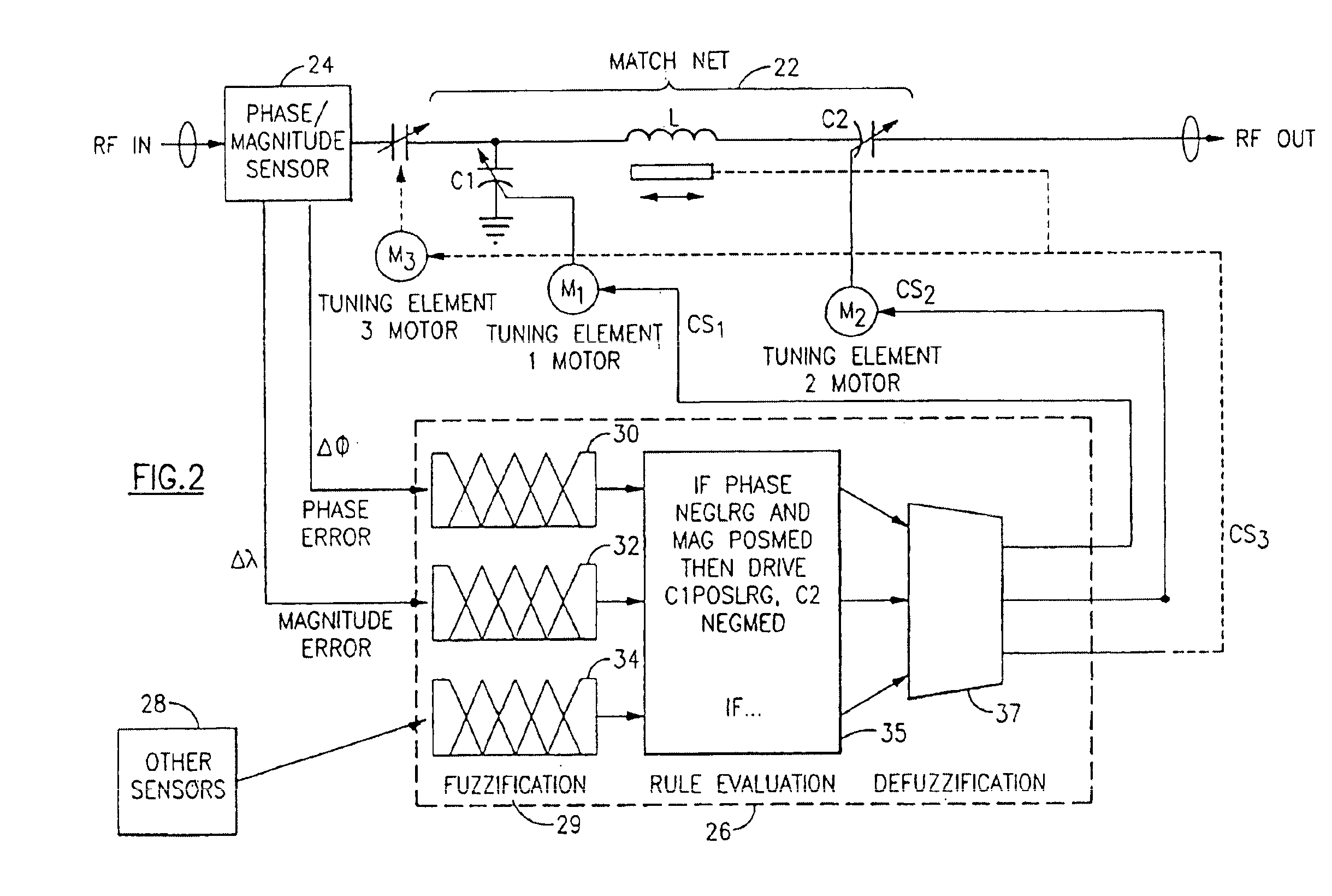
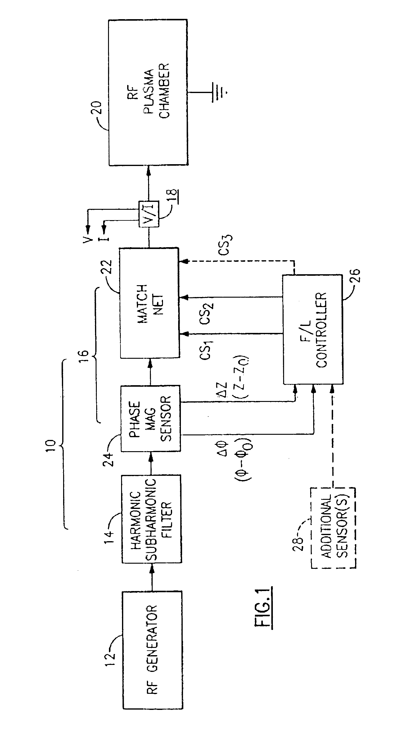
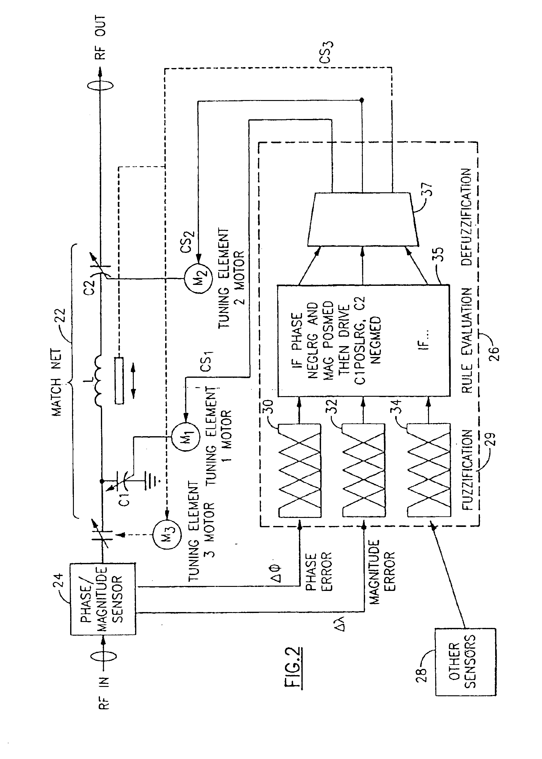
[0027]With reference to the Drawing figures, and initially to FIG. 1, an RF plasma processing system 10 is shown for purposes of example. A plasma generator 12 provides RF electrical power at a predetermined frequency, i.e., 13.56 MHz. The output of the generator 12 is followed by a harmonic / subharmonic filter 14, which is then followed by an impedance matching network 16, which supplies the electrical power through a voltage / current sensor system 18 to an input of a plasma chamber 20. The matching network 16 comprises a controllable impedance matching unit 22, with a phase / magnitude sensor 24 connected at its input. The sensor provides a phase error signal Δφ that is proportional to the difference between the nominal input impedance phase angle and the actual phase angle (φ-φo) of the impedance matching unit, and also provides a magnitude error signal ΔZ that is proportional to the difference between the nominal input impedance and actual input impedance (Z-Zo).

[0028]A fuzzy logic ...


PUM


Abstract

A fuzzy logic control arrangement is provided for an impedance match network of the type that is typically employed between a source of RF power at a given impedance, e.g., 50 ohms, and a non-linear load whose impedance can vary in magnitude and phase, e.g., an RF plasma. The fuzzy logic controller fuzzifies the phase and the magnitude error signals. The error signals are applied to a fuzzy logic interference function based on a number of fuzzy sets. The values of the error signals enjoy some degree of membership in one or more fuzzy sets. Fuzzy logic rules are applied to the phase and magnitude error signals. In a defuzzification stage, drive signal values are obtained for moving the tuning elements of the variable impedances. The drive signal values are weighted according to respective fuzzy inference functions for which the error signals enjoy membership. Then the weighted drive signal values are combined to produce output drive signals.

Description

BACKGROUND OF THE INVENTION[0001]This invention relates to plasma generation equipment, and is particularly directed to an automatic RF matching network to match the impedance of a reactive plasma chamber or similar non-linear load to a constant impedance (e.g., 50 ohms) output of an RF generator or similar RF source. The invention is more particularly concerned with a fuzzy logic technique that is capable of controlling two, or more, tunable elements in the matching network using both the phase error signal and magnitude error signal associated with the matching network.[0002]In a typical RF plasma generator arrangement, a high power RF source produces an RF wave at a preset frequency, i.e., 13.56 MHZ, and this is furnished along a power conduit to a plasma chamber. The RF power is also typically provided at a fixed, known impedance, e.g., 50 ohms. Because there is typically a severe impedance mismatch between the RF power source and the plasma chamber, an impedance matching networ...

Claims


Application Information

Patent Timeline
Patent Type & Authority Patents(United States)
IPC IPC(8): H01P5/08G05B13/02H05H1/46
CPCG05B13/0275H05H1/46H03H7/40
Inventor HARNETT, SEAN
Owner MKS INSTR INC
Why Eureka
Try Eureka