Flexible thin layer open electrochemical cell

Inactive Publication Date: 2007-06-05
PAUEHR PEHJPER
View PDF38 Cites 19 Cited by
  • Summary
  • Abstract
  • Description
  • Claims
  • Application Information

AI Technical Summary

Benefits of technology

[0035]The present invention successfully addresses the short-comings of the presently known configurations by providing a flexible thin layer open electrochemical cell which does not accumulate gases upon storage, yet it is maintained wet and intact by the use of a deliquescent material for keeping it wet at all times and a watersoluble polymer for obtaining the required viscosity for adhering

Problems solved by technology

Although solid state batteries have an inherent advantage, they do not dry out and do not leak, they suffer major disadvantages when compared with liquid state batteries since, due to limited diffusion rates of ions through a solid, their operation is temperature dependent to a much larger extent, and many operate well only under elevated temperatures.
Being clo

Method used


Image

  • Flexible thin layer open electrochemical cell
  • Flexible thin layer open electrochemical cell
  • Flexible thin layer open electrochemical cell

Examples


example 1

[0061]A solution containing 120 mg of polyvinylalcohol (an aqueous soluble polymer) and 1680 mg of zinc-chloride (a deliquescent material and an electroactive soluble material) in 1.2 ml of water was prepared. This solution had a glue like viscous appearance. A 4.5 cm×7 cm strip of a filter paper was thoroughly wetted with this solution by a printing or dipping technologies. A mixture of 300 mg zinc powder with the above solution was prepared and was printed on one side of the paper strip serving as the negative pole layer. On the other side printed was a mixture of 250 mg manganese-dioxide and 50 mg of a conductive carbon powder, together with the above solution, serving as the positive pole layer. When electrical contacts were made with both sides and were connected over a load an electrical current was measured. A current of 12 microampers per cm2 at a voltage of 1.7+1.2 volts was easily maintained for five days continuously under room conditions.

example 2

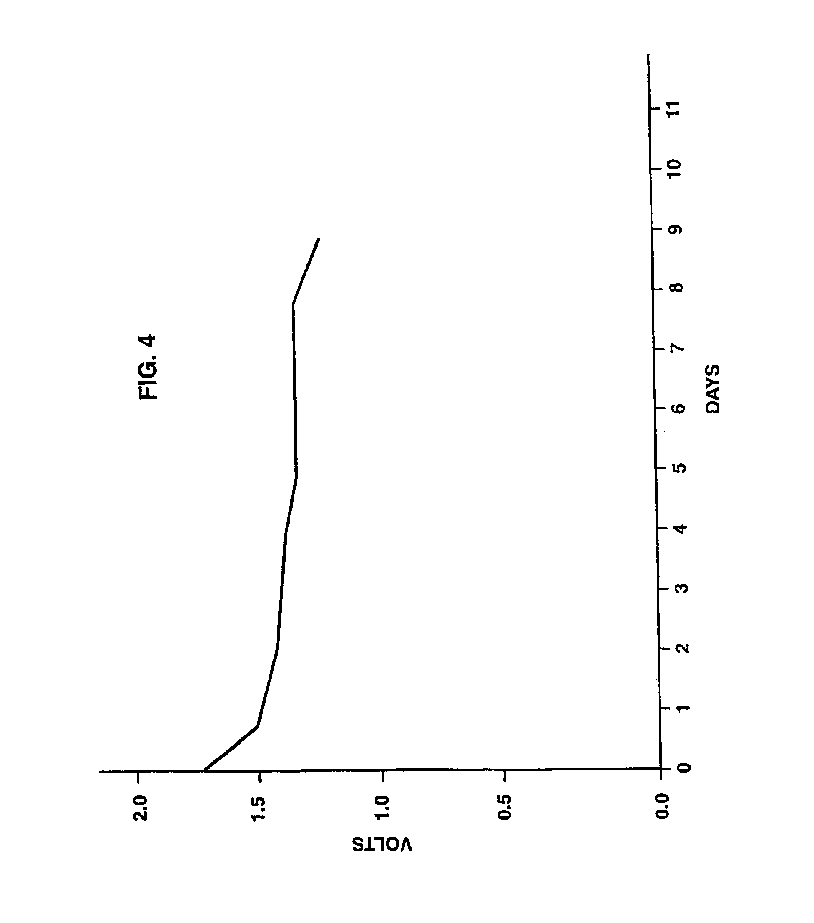
[0062]An open cell was prepared as described under Example 1 above and was connected to a voltmeter. As shown in FIG. 4, measurement of the voltage produced by the cell under room conditions revealed a pronounced voltage of 1.7+1.2 sustained for nine successive days.

example 3

[0063]A saturated potassium-hydroxide solution is prepared and brought to the viscosity of a glue by mixing with a water soluble polymer. A porous substance (e.g., a filter paper) is thoroughly wetted with this solution and a mixture of the solution with nickel-oxide powder is pasted on one side of the porous substance to form a positive pole layer and, a similar mixture with cadmium powder is pasted on the other side of the porous substance to form a negative pole layer. By connecting a voltmeter to the two sides a voltage of 1.2 volts is measured and a high current is measured when the two layers are contacted over a load. The cell does not dry out in the open and can be recharged if so desired.


PUM

PropertyMeasurementUnit
Currentaaaaaaaaaa
Electrical conductivityaaaaaaaaaa
Viscosityaaaaaaaaaa

Abstract

A flexible thin layer open liquid state electrochemical cell which can be used as a primary or rechargeable power supply for various miniaturized and portable electrically powered devices of compact design. The cell includes a wet electrolyte, yet maintains a fexible, thin and open configuration, thus devoid of accumulation of gases upon storage. The cell comprising a first layer of insoluble negative pole, a second layer of insoluble positive pole and a third layer of aqueous electrolyte, the third layer being disposed between the first and second layers and including a deliquescent material for keeping the open cell wet at all times; an electroactive soluble material for obtaining required ionic conductivity; and, a watersoluble polymer for obtaining a required viscosity for adhering the first and second layers to the third layer. The electrochemical cell of the present invention is preferably produced using a suitable printing technology.

Description

[0001]This is a continuation of application U.S. patent application Ser. No. 08 / 575,190, filed Dec. 20, 1995 now U.S. Pat. No. 5,652,043.FIELD AND BACKGROUND OF THE INVENTION[0002]The present invention relates to electrochemical cells which are used as battery power sources by converting chemical energy to electrical energy. More particularly, the present invention relates to a primary or rechargeable electrochemical cell to be used as a regular or rechargeable battery which accomplishes the conversion of chemical energy to electrical energy using a wet (e.g., liquid state) electrolyte, yet maintains a flexible thin layer and open configuration.[0003]The ever-growing development of miniaturized and portable electrically powered devices of compact design such as, for example, cellular phones, voice recording and playing devices, watches, motion and still cameras, liquid crystal displays, electronic calculators, IC cards, temperature sensors, hearing aids, pressure sensitive buzzers, ...

Claims


Application Information

Patent Timeline
IPC IPC(8): H01M6/00H01M4/66A61B5/00A61N1/30B65D51/24H01M4/02H01M4/08H01M4/12H01M4/20H01M4/26H01M4/62H01M6/06H01M6/12H01M6/18H01M6/22H01M6/40H01M6/42H01M6/46H01M6/48H01M8/00H01M10/00H01M10/02H01M10/04H01M10/10H01M10/12H01M10/26H01M10/30H01M50/50
CPCA61B5/14532B65D51/248H01M2/0257H01M2/0275H01M6/12H01M6/181H01M6/22H01M6/40H01M10/0436H01M10/127A61N1/30Y10T428/24926H01M2/16H01M2/20H01M4/02H01M4/621H01M6/42H01M6/48H01M2300/0002H01M2300/0014H01M2300/0085Y02E60/126Y02E60/124Y10T428/24917Y02E60/10H01M50/50Y02P70/50B32B3/00H01M6/00
Inventor NITZAN, ZVI
Owner PAUEHR PEHJPER
Why Eureka
Try Eureka