Method and device for removing gaseous pollutants from exhaust gases

A pollutant and exhaust gas technology, applied in the field of removing gaseous pollutants, can solve problems such as large pressure loss, low utilization rate of reaction reagents, and problems caused by control operations

Inactive Publication Date: 2008-03-05
OUTOKUMPU OY
View PDF0 Cites 0 Cited by
  • Summary
  • Abstract
  • Description
  • Claims
  • Application Information

AI Technical Summary

Problems solved by technology

[0003] Compared with fixed fluidized bed, circulating fluidized bed has better mass transfer and heat transfer conditions because of high fluidization degree, and can integrate suspension heat exchanger, but its solid residence time is limited
Especially in the case of fluctuating exhaust gas volumes, this can lead to problems in control operation
Disadvantages are also high pressure loss and, in some cases, low utilization of reagents

Method used


Image

  • Method and device for removing gaseous pollutants from exhaust gases
  • Method and device for removing gaseous pollutants from exhaust gases
  • Method and device for removing gaseous pollutants from exhaust gases

Examples


Embodiment 1

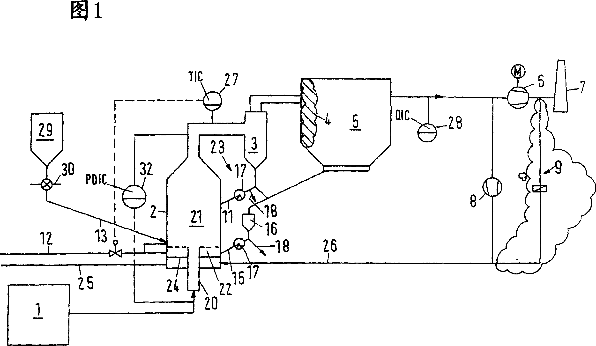
[0054] Because the high turbulence and associated good mass and heat transfer conditions create good reaction conditions in the mixing chamber 21, and because the reagents have a long residence time in the fluidized bed, the reaction with almost stoichiometric consumption The reagents then allow the dry exhaust gas cleaning reaction to proceed to very low cleaning gas concentrations according to the invention. In this way, a particularly effective exhaust gas cleaning can be achieved with a very low consumption of reagents. In addition to the above-mentioned applications, the gas cleaning method of the present invention can also be used to clean the SO-containing gas discharged from the sintering plant 2 exhaust gas. Example 1 (removal of hydrogen fluoride from the waste gas stream discharged from an electrolytic cell for the production of aluminum)

[0055] When the electrolytic aluminum is melted, a large amount of gaseous hydrogen fluoride (HF) is released. This pollutan...

Embodiment 2

[0066] Embodiment 2 (removal of acid gas from the flue gas flow of combustion plant)

[0067] During the combustion process, the sulfur, fluorine and chlorine compounds in the fuel are basically converted into sulfur dioxide (SO) through various equilibrium reactions 2 , hydrogen fluoride HF and hydrogen chloride HCl. This occurs, for example, in power plants and incineration plants for waste or special waste. These gaseous compounds exit the combustion zone 1 with the exhaust gas, from which they must be removed before being released into the atmosphere.

[0068] For the removal of acidic components from exhaust gases (flue gases), various wet, dry and semi-dry methods have been developed. What all methods have in common is the simultaneous removal of acidic components with alkaline reagents.

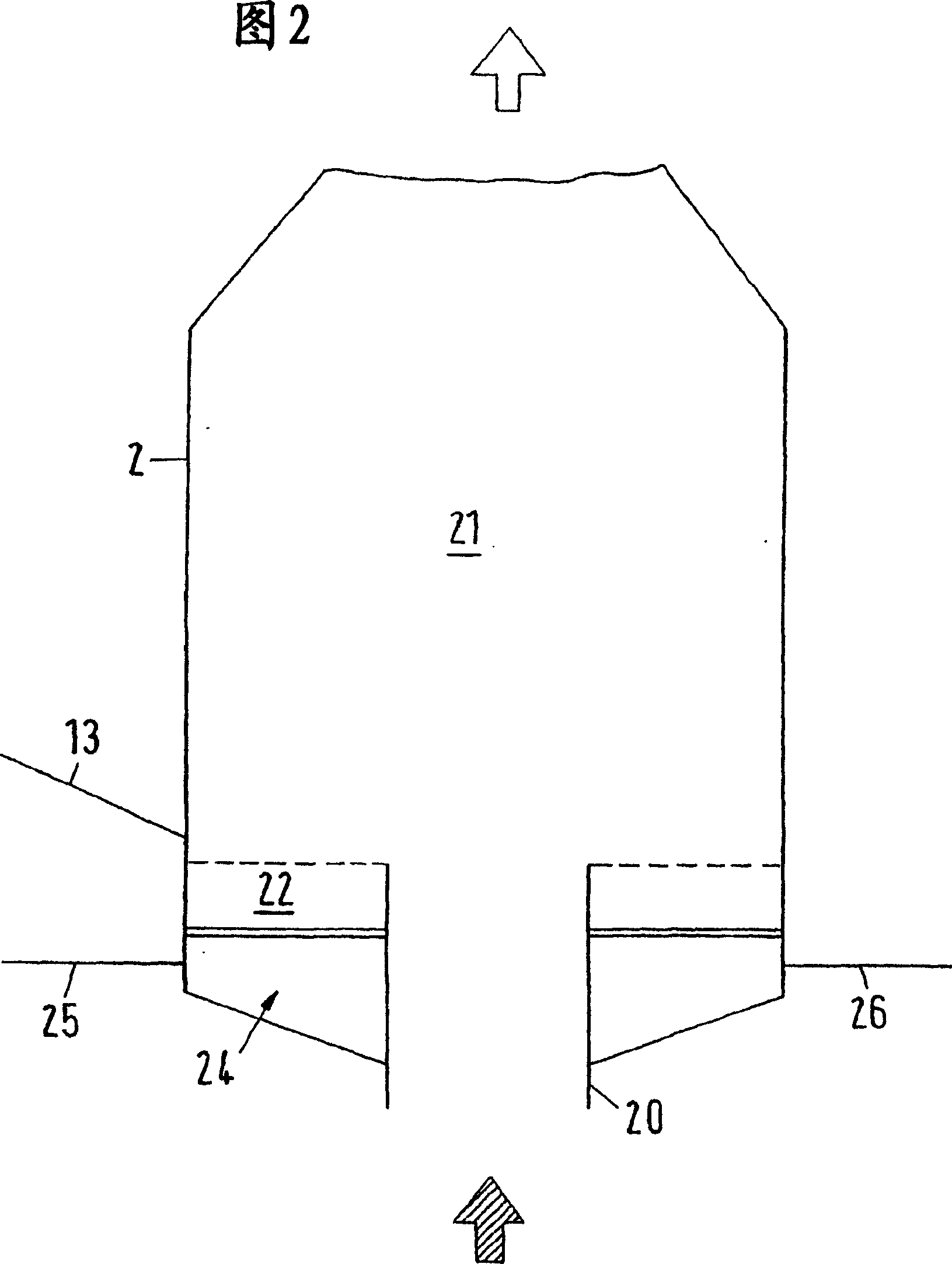
[0069] The exhaust gas flow discharged from the combustion device 1 is supplied to the center pipe 20 (central tuyeres). The temperature at the inlet of the central tube 20 is abou...

Embodiment 3

[0079] Example 3 (removal of sulfur dioxide, hydrogen fluoride and hydrogen chloride from the exhaust gas stream of the heat generating process)

[0080] In some production processes, such as glass production, cement production, sintering devices and metallurgical processes, clean harmful gases are released during the production process. For cleaning the gas, a method substantially similar to that described above for the combustion device is used. But in many industrial fields, lower efficiencies or higher emissions are allowed.

[0081] In this example, the exhaust gas stream discharged during the production process is supplied to the central pipe 20 of the reactor 2 . The temperature at the inlet of the central tube is about 200-600°C. The annular fluidized bed 22 is supplied with recirculated clean gas or particle-free off-gas from parallel ducted gas streams, if available.

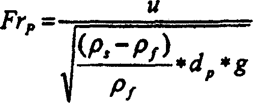
[0082] Particle Froude number Fr in central tube 20 p About 77, the particle Froude number Fr i...


PUM


Abstract

The present invention relates to a method for removing gaseous pollutants from exhaust gases, in which the gaseous pollutants react with a fine-grained reactant by forming solids in a fluidized-bed reactor (2), and to a corresponding plant. To achieve low pollutant concentrations in the clean gas with an almost stoichiometric consumption of reactant, it is proposed to introduce the exhaust gas from below through a preferably central gas supply tube (20) into a mixing chamber (21) of the reactor (2), the gas supply tube (20) being at least partly surrounded by a stationary annular fluidized bed (22) of reactant, which bed is fluidized by supplying fluidizing gas, and to adjust the the gas velocities of the exhaust gas and of the fluidizing gas for the annular fluidized bed (22) such that the Particle-Froude-Numbers in the gas supply tube (20) are between 1 and 100, in the annular fluidized bed (22) between 0.02 and 2, and in the mixing chamber (21) between 0.3 and 30.

Description

technical field [0001] The invention relates to a method for removing gaseous pollutants from waste gas, wherein the gaseous pollutants and fine-grained reagents react in a fluidized bed reactor to form solids, and to a corresponding device. Background technique [0002] These methods and devices are suitable, for example, for the removal of acid gases such as SO from gas streams produced by combustion plants such as power plants, waste and special waste incineration plants or other heat producing processes such as the production of aluminum in electrolytic cells 2 , HF and HCl. For this purpose, a number of different wet, dry and semi-dry methods have been developed, in which the removal of acidic components is carried out by adding alkaline reagents. In the case of the dry process, entrained bed and fluidized bed methods are used, especially those using circulating Venturi-type fluidized beds. [0003] Compared with the fixed fluidized bed, the circulating fluidized bed ...

Claims


Application Information

Patent Timeline
Patent Type & Authority Patents(China)
IPC IPC(8): B01D53/12B01J8/18B01J8/24B01D53/50B01D53/68
CPCB01D53/685B01J8/1809B01D53/508B01J8/1818B01J8/1863B01J2208/00725B01J2208/00548B01D53/12B01J8/18B01J8/24
Inventor M·施特勒德S·斯内德K·哈塞尔万德
Owner OUTOKUMPU OY
Why Eureka
Try Eureka