
Vehicle conductor device with voltage stabilizing surge prevention character

A surge and vehicle technology, applied to circuit devices, vehicle components, battery circuit devices, etc., can solve the problem of vibration and sound, such as heat dissipation motors, electromagnetic chucks for controlling motors and air-conditioning compressors, current and voltage transmission time delays, Inaccurate fuel injector control signals and other problems, to achieve stable voltage, sensitive braking effect, and accurate ignition timing

Inactive Publication Date: 2008-08-27
苏 志扬
View PDF5 Cites 0 Cited by
  • Summary
  • Abstract
  • Description
  • Claims
  • Application Information

AI Technical Summary

Problems solved by technology

[0002] With the rapid development of vehicle technology, a large number of electronic control products are used in the control of vehicles in order to achieve the maximum efficiency of vehicle operation, but the electronic signal will be changed by the ambient temperature, metal fatigue or increase the impedance value of the conductive medium, which will cause Electronic signal level error, and the impact of large surge, chain wave current and voltage from the vehicle generator when starting, will also cause electronic signal error, and even damage electronic products
[0003] The steel structure body of the vehicle is designed to conduct ground current, but the conduction resistance value of the steel material will change with the increase of temperature and the long service life, resulting in the "signal level" transmitted from the sensor to the driving computer (ECU). "Change, the signal level is processed by the driving computer, and then transmitted to the signal level of the control components. The time is also incorrect, which reduces the overall efficiency of the vehicle, such as the ignition signal of the vehicle engine.
[0004] Improper signal level will cause the vehicle to vibrate and rattle, and the fuel injector control signal will be inaccurate, which will easily cause the vaporized gas to be too thick or too thin, resulting in incomplete combustion of the engine room and more polluting exhaust gas
Moreover, the large surge and chain wave current from the generator will cause the DC motor on the vehicle to produce vibration sounds when rotating, such as the vibration sound of the heat dissipation motor, control motor and electromagnetic sucker of the air-conditioning compressor, and even a large current The surge will destroy the circuit of electronic components, generate electromagnetic waves, etc.
[0005] The energy-saving device of a general vehicle has the following main features: connect the negative pole of the battery through several special magnet electric wires, and use the magnet electric wires to conduct the negative electrode impedance of the vehicle circuit system back to each contact on the vehicle, so that the ohm value of the circuit is reduced. The main disadvantages in its composition are: 1. when the vehicle is running dynamically, the electric power is provided by the generator, and the battery is charged at this time, and the grounding current is provided by the negative pole of the generator instead of the negative pole of the battery; But at the same time, it also increases the surge current of the generator because the grounding resistance becomes smaller, which will cause greater damage to the electrical system in the vehicle, such as electronic circuit components such as the driving computer air flow sensor; ③The grounding of the magnet electric wire will cause current and The transmission time delay of the voltage, the use current of each current-consuming device is different, and the time delay caused by the same magnet electric wire is also different, which makes the time consistency between the systems worse, and the overall benefit of the vehicle is reduced, such as Ignition time, fuel injection time of fuel injector, etc.

Method used


Image

  • Vehicle conductor device with voltage stabilizing surge prevention character
  • Vehicle conductor device with voltage stabilizing surge prevention character
  • Vehicle conductor device with voltage stabilizing surge prevention character

Examples


Embodiment Construction

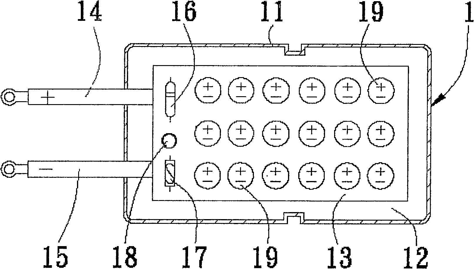
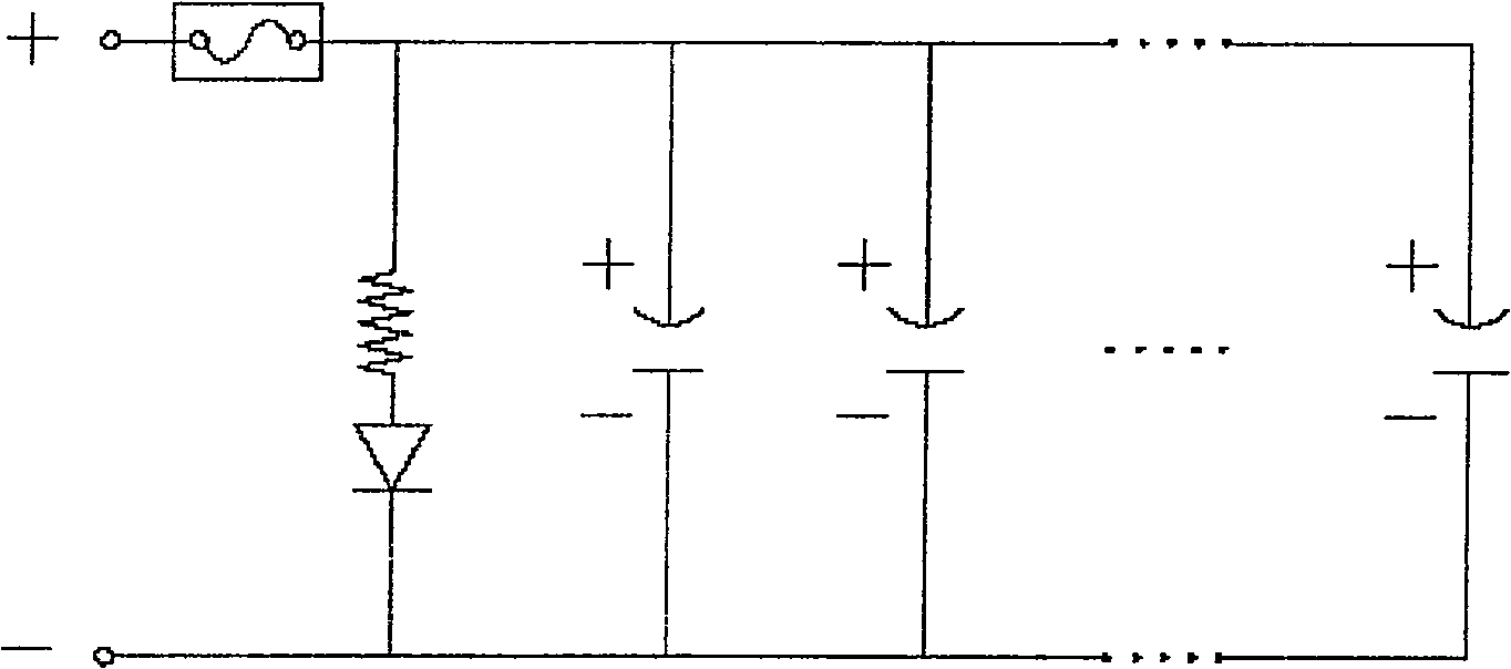
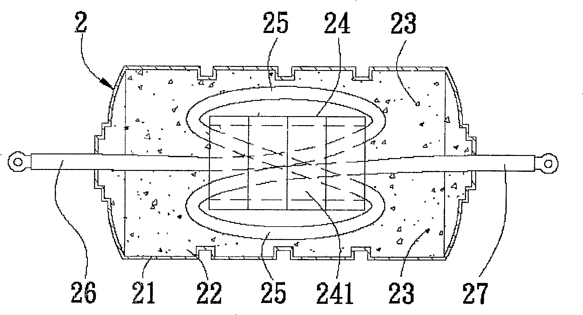
[0057] see Figure 1 to Figure 8 , the vehicle wire device with voltage stabilization and anti-surge provided by the present invention is additionally installed in the vehicle engine room 4, and does not change the safety structure of the vehicle, and then connects with the generator 41, the gearbox controller 42, the engine Upper cover 43, battery 44, starter motor 45, anti-lock brake motor 46, trip computer 47, throttle controller 48, instrument panel grounding wire assembly 49, compressor 50, relay assembly 51 and car body The grounding point 52 forms a closed annular grounding circuit, which mainly includes: a closed annular grounding circuit of a surge attenuator 1, a surge suppressor 2 and multiple branch contacts; The first conductor wire 26 of the device 2 is connected to the electric wire 3 that is connected to the positive pole of the battery 44, and its negative pole electric wire 15 is connected to the negative pole of the generator 41; and the second conductor wir...


PUM


Abstract

A voltage stabilizing and surge preventing vehicle grounding system is essentially constructed of a surge absorber, a surge suppresser, and a multi-taped close loop grounding wire. The positive terminal of the surge absorber is connected to a first conductor of the surge suppresser, whereas the negative terminal of the surge absorber is connected to the negative terminal of the vehicle generator. A second conductor of the surge suppresser is connected to the positive terminal of the vehicle generator so as to stabilize the output voltage of the generator and prevent the impulse surge from the generator. The grounding wire is formed into a closed loop consisting of a first half side and a second half side, and tapped off from the modes en route to ground the negative terminals of the component devices of the vehicle along with the chassis so as to minimize the grounding resistance thereby further stabilizing the generator voltage and improving engine efficiency and signal precision of the computer that helps upgrade the response of the mechanical components of the vehicle to the computer signal.

Description

technical field [0001] The invention relates to a vehicle wire device with voltage stabilization and anti-surge, especially a device that can suppress the large current surge and chain wave generated by the generator, and attenuate the surge and chain wave current to stabilize the output of the generator. A vehicle wire device for voltage and current and a wiring method thereof. Background technique [0002] With the rapid development of vehicle technology, a large number of electronic control products are used in the control of vehicles in order to achieve the maximum efficiency of vehicle operation, but the electronic signal will be changed by the ambient temperature, metal fatigue or increase the impedance value of the conductive medium, which will cause Electronic signal level error, and the impact of large surge, chain wave current and voltage from the vehicle generator when starting, will also cause electronic signal error, and even damage electronic products. [0003...

Claims


Application Information

Patent Timeline
Patent Type & Authority Patents(China)
IPC IPC(8): B60R16/02H02J7/00H02J7/14H02H9/00H01F37/00H01F38/00
CPCB60R16/06
Inventor 苏志扬
Owner 苏 志扬
Learn More