Method for precipitating large area amorphous, nanocrystalline alloy layer using magnesium alloy surface glow plasma

A glow plasma and nanocrystalline alloy technology, applied in ion implantation plating, metal material coating process, coating, etc., can solve the problems of poor protection of passivation film, shedding of protective layer, corrosion of magnesium alloy, etc., and achieve super Good plasticity, improved corrosion resistance, and excellent corrosion resistance

Inactive Publication Date: 2007-08-01
NANJING UNIV OF AERONAUTICS & ASTRONAUTICS
View PDF1 Cites 10 Cited by
  • Summary
  • Abstract
  • Description
  • Claims
  • Application Information

AI Technical Summary

Problems solved by technology

However, there are various defects and deficiencies in these methods or surface technologies: 1. Because the film layer and the magnesium alloy substrate are only connected together by physical adsorption or mechanical bonding, it is easy to cause the protective layer to fall off and cause serious corrosion of the magnesium alloy; 2. .These surface protective layers have no obvious passivation phenomenon or a small passivation interval during the electrochemical corrosion process, which proves that there is no passivation film formed or the protection of the passivation film is poor during the corrosion process

Method used


Image

  • Method for precipitating large area amorphous, nanocrystalline alloy layer using magnesium alloy surface glow plasma
  • Method for precipitating large area amorphous, nanocrystalline alloy layer using magnesium alloy surface glow plasma

Examples


example 1

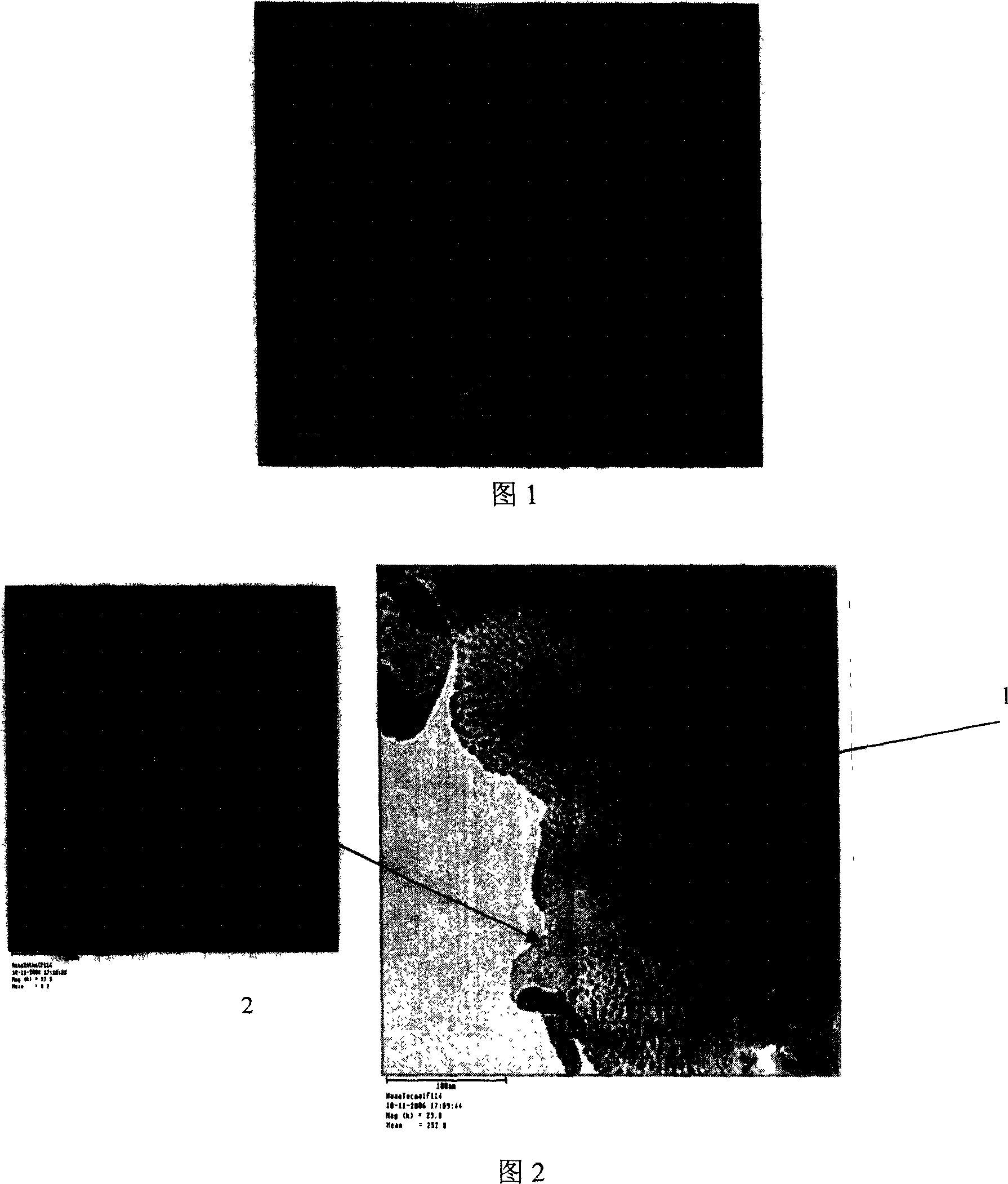
[0016] Pure aluminum is used as the target material, its melting point is around 650°C, and magnesium alloy AZ31 is used as the workpiece. The deposition process is as follows: the target material is 600V, the workpiece voltage is 300V, the air pressure is 30Pa, the distance between the target material and the workpiece is 35mm, and the deposition time is 3h. Figure 1 shows the β-Al formed on the surface of AZ31 magnesium alloy 2 Mg amorphous, subsurface β-Al 2 SEM pictures of Mg nanocrystals. Figure 2 is a transmission electron micrograph of the glow sputtering deposited layer. Observation by transmission electron microscope can prove that the surface of the deposited layer has an amorphous structure (diffraction pattern is a typical amorphous halo), while the subsurface layer is nanocrystalline, and its grain size is less than 5nm. The electrochemical performance test results of the sputtered deposition layer in 3.5% NaCl solution show that the natural corrosion potential ...

example 2

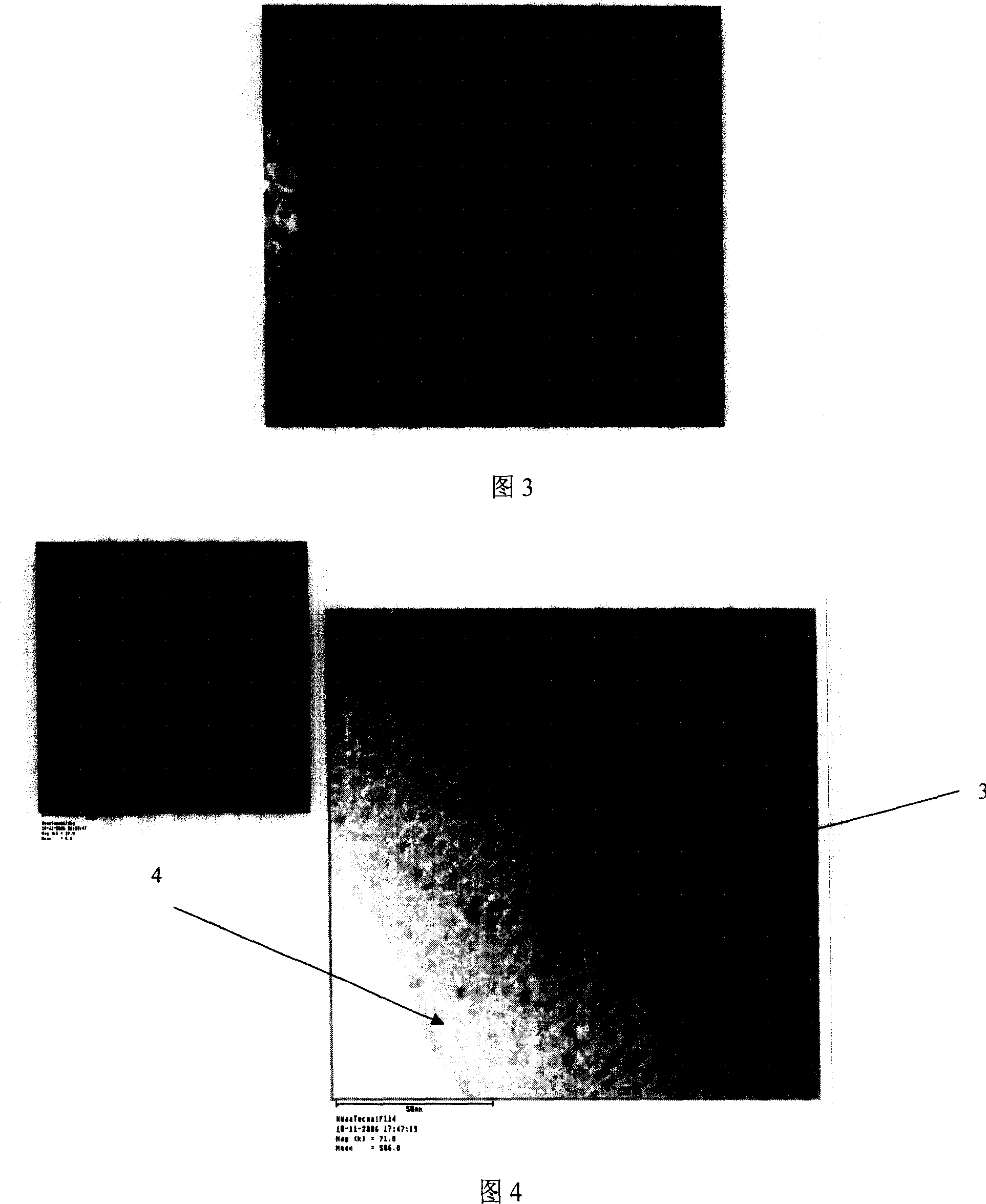
[0018] The HastelloyC-2000 alloy is used as the target material, its melting point is around 1300°C, the magnesium alloy AZ31 is used as the workpiece, the deposition process is as follows: the target material is 600V, the workpiece voltage is 300V, the air pressure is 30Pa, the distance between the target material and the workpiece is 35mm, and the deposition time is 3h . Figure 3 is the SEM photo of Ni-Cr-Mo-Cu amorphous and subsurface nanocrystals formed on the surface of AZ31 magnesium alloy (the deposition process is: target 600V, workpiece voltage 300V, air pressure 30Pa, distance between target and workpiece 35mm, deposition time 3h). Figure 4 is a transmission electron micrograph of the glow sputtering deposited layer. Observation by transmission electron microscope can prove that the surface of the deposited layer is amorphous (diffraction pattern is a typical amorphous halo), while the subsurface layer is nanocrystalline structure, and its grain size is less than 10...


PUM

PropertyMeasurementUnit
melting pointaaaaaaaaaa
densityaaaaaaaaaa
particle sizeaaaaaaaaaa

Abstract

The invention provides a method for settling corrosion-proof amorphous nanocrystalline alloying layer with magnesium alloy surface glow plasma, which is suited for preparing corrosion-proof modified layer for magnesium alloysurface, belonging to field of advanced light alloy surface corrosion- proof technology. It is characterized in that it takes bicathode glow sputtering device composed of target electrode and workpiece electrode and the method, and said target material comprises pure metal or its alloy material with its fusion point being 600- 1800 Deg. C, the target material voltage is 300- 650V, working voltage is 300- 450 V, the distance between target material and workpiece is 30 -40 mm, air pressure (Ar gas) is 20- 45 Pa. The deposited layer possesses outstanding corrosion resistant preformance.

Description

technical field [0001] The invention provides a method for glow plasma deposition of a corrosion-resistant amorphous and nanocrystalline alloy layer on the surface of a magnesium alloy, which is suitable for preparing a corrosion-resistant modified layer on the surface of a magnesium alloy, and belongs to the technical field of advanced light alloy surface corrosion resistance protection. Background technique [0002] Magnesium is the lightest metal among structural materials, with a density of 1.74g / cm 3 , which is about 2 / 3 of aluminum alloy and 1 / 4 of steel, and is abundant and widely distributed in the earth's crust, accounting for about 2.35% of the earth's weight. Compared with other common engineering materials, magnesium alloy has many advantages, such as: high specific strength and specific stiffness; excellent thermal conductivity and electrical conductivity; non-magnetic and electromagnetic shielding properties; good damping, cutting performance, extrusion Formab...

Claims


Application Information

Patent Timeline
Patent Type & Authority Applications(China)
IPC IPC(8): C23C14/38C23C14/54C23C14/14
Inventor 徐江徐重陶杰张平则刘子利陈哲源朱文慧骆心怡
Owner NANJING UNIV OF AERONAUTICS & ASTRONAUTICS
Why Eureka
Try Eureka