Sinter cooler low temperature waste gas residual heat boiler and power generating system thereof

A technology of sintering cooler and waste heat boiler, which is applied to steam boilers, steam boiler accessories, components of steam boilers, etc. Low loss, low heat transfer effect, light weight effect

Inactive Publication Date: 2007-08-22
JIANGSU DONGJIU HEAVY IND
View PDF0 Cites 22 Cited by
  • Summary
  • Abstract
  • Description
  • Claims
  • Application Information

AI Technical Summary

Problems solved by technology

The exhaust gas temperature of the boiler is above 200°C, the waste heat utilization rate of the waste gas is low, and a large sinter cooler needs to arrange many sets of small-capacity heat pipe waste heat boilers to operate, which is inconvenient for maintenance and management
Neither of these two methods can fundamentally solve the problem of high energy consumption of sintering machines

Method used


Image

  • Sinter cooler low temperature waste gas residual heat boiler and power generating system thereof
  • Sinter cooler low temperature waste gas residual heat boiler and power generating system thereof
  • Sinter cooler low temperature waste gas residual heat boiler and power generating system thereof

Examples


Embodiment 1

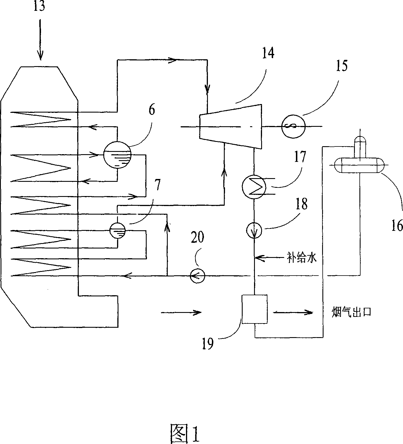
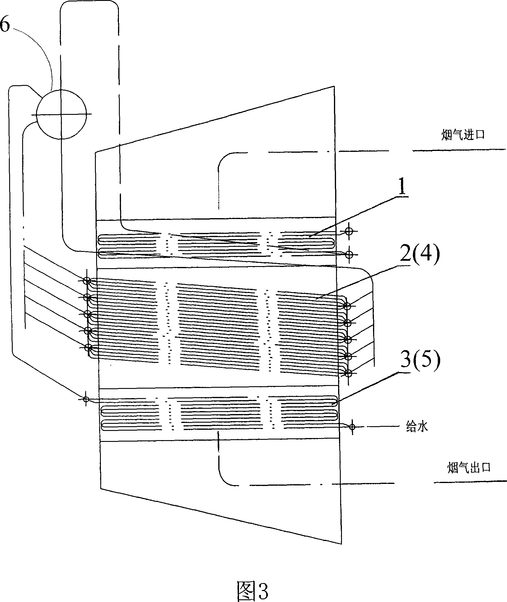
[0041] Dual-pressure system: a dual-pressure single-stage supplementary steam system using a supplementary steam turbine. The waste heat boiler is equipped with a superheater 1, an evaporation zone 2, a low-pressure evaporation zone 4, a soft water heater (economizer) 3, and a low-pressure soft water heater (low pressure Economizer) 5, flue gas passes through superheater 1, evaporation zone 2, low pressure evaporation zone 4, soft water heater (coal economizer) 3, low pressure soft water heater (low pressure economizer) 5 from top to bottom. The sintering waste heat boiler produces two kinds of steam with different parameters, one is main steam and the other is low-pressure supplementary steam. Due to the low-pressure evaporation section, the low-pressure steam pressure is 0.55MPa, the saturation temperature of the low-pressure steam is 162°C, and the exhaust gas temperature can drop to about 110°C.

Embodiment 2

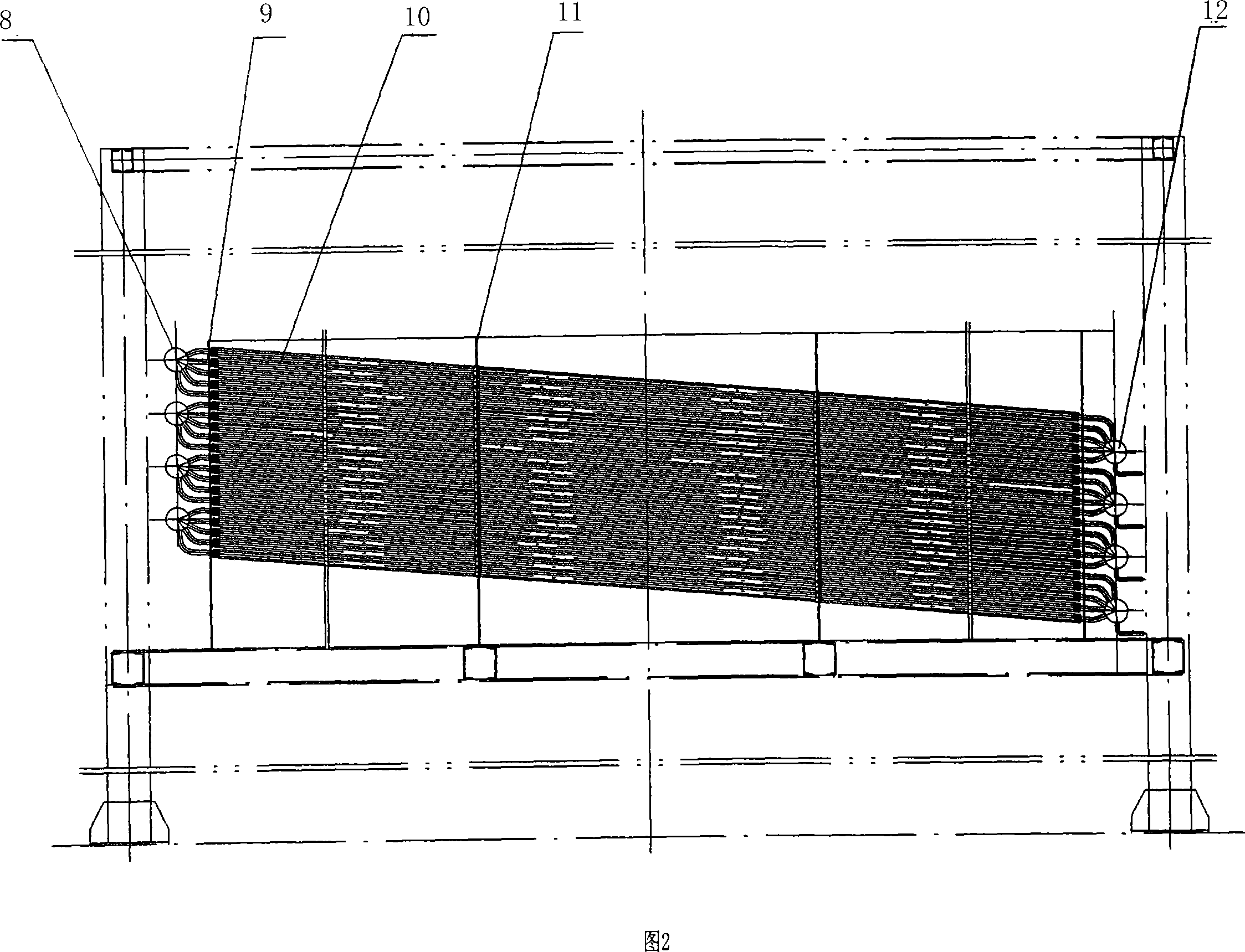
[0043] In Fig. 2, the steam-water mixture produced in the evaporation zone 2 is collected into the upper header 8 and enters the waste heat boiler drum 6 through the outlet pipe, and the water supply in the evaporation zone 2 is distributed to the lower header 12 by the steam drum 6 through the downcomer. , thus forming a reliable water circulation loop. The steam drum 6 separates the steam-water mixture, and the saturated steam enters the superheater 1 to be heated into superheated steam. The heating surfaces of the economizers 3 and 5 adopt the structure of spiral finned tubes 10, and the feed water enters the steam drums 6 and 7 after being heated.

[0044] In Fig. 3, the evaporation section 2 is designed as a lantern tube structure, that is, the upper and lower headers 8, 12 and the convection tube bundle 10 structure.

Embodiment 3

[0046] A low-temperature exhaust gas waste heat boiler with a sintered cooler, including a superheater, an evaporation zone, a low-pressure evaporation zone, an economizer, and a low-pressure economizer. There are connecting flues and water vapor pipes between the equipment. The waste heat boiler adopts a vertical layout as a whole. Tube box structure, the boiler tube box is equipped with superheater 1, evaporation area 2, low pressure evaporation area 4, economizer 3 and low pressure economizer 5 from top to bottom, among which the evaporation area and low pressure evaporation area are equipped with multiple Group evaporator, the evaporator is placed obliquely in the flue, the inclination angle is 5°~15°; the evaporator is a lantern tube structure, the evaporator is equipped with an upper header, a lower header and a convection tube bundle, the upper and lower headers The staggered convection tube bundles are formed by longitudinal rows of spiral finned tubes. Each evaporator ...


PUM


Abstract

The present invention provides an exhaust-heat boiler capable of effectively utilizing low-temperature heat transmission to make power generation and its power generation system. Said exhaust-heat boiler whole body adopts vertical type arrangement and tube-box type structure, in the boiler tube-box interior are successively set super heater, evaporation zone, low-pressure evaporation zone, coal economizer and low-pressure coal economizer from top to bottom, in which the evaporation zone and low-pressure evaporation zone have several groups of evaporators, these evaporators are obliquely placed in smoke flue, their inclination angle is 5 deg-15 deg. Said invention also provides the concrete structure of every evaporator, and provides the working principle of said exhaust-heat boiler and its power generation system and their concrete operation method.

Description

1. Technical field [0001] The invention belongs to boiler equipment and its application, in particular to a sintered cooler low-temperature exhaust gas waste heat boiler and its power generation system. 2. Background technology [0002] Existing technology: "National Key Industry Cleaner Production Technology Guidance Catalogue" Guo Jingmao Zi [2000] No. 137 (the first batch) and the State Economic and Trade Commission and the State Environmental Protection Administration Joint Announcement [2003] No. 21 (the second batch) issued 28 clean production technologies directly related to the steel industry. From coking, ironmaking, steelmaking, and steel rolling production technologies, select the most representative indicators that can best reflect the clean production achievements of iron and steel complexes and reflect the "energy saving" and "pollution reduction" of the iron and steel industry, and the recovery of sintering waste heat is set as one of them one item. The sint...

Claims


Application Information

Patent Timeline
Patent Type & Authority Applications(China)
IPC IPC(8): F22B1/16F22B37/02
Inventor 陈长景张兰芳王志龙龚来广程立春曹华
Owner JIANGSU DONGJIU HEAVY IND
Why Eureka
Try Eureka