

Device and method for purifying flue gas
A purification device and flue gas purification technology, applied in chemical instruments and methods, separation methods, sulfur trioxide/sulfuric acid, etc., can solve the problems of increasing the complexity of the structure of the desulfurization tower, and achieve excellent corrosion resistance and short construction period Effect
- Summary
- Abstract
- Description
- Claims
- Application Information
AI Technical Summary
Problems solved by technology
Method used
Image

Examples
Embodiment 1
[0098] A 440T / h fluidized bed boiler, burning coal with a sulfur content of 1.5%, and a flue gas flow rate of 500,000 Nm 3 / hr, SO 2 The content is 3200mg / Nm 3 , the content of other pollutants in the flue gas is: dust = 80mg / Nm 3 , SO 3 =55mg / Nm 3 , HCl=35mg / Nm 3 , HF=20mg / Nm 3 , NOx=100mg / Nm 3 , the flue gas temperature is 120°C.
[0099] In this embodiment, the ammonia method is used for desulfurization and purification. The desulfurization raw material is an ammonia water mixture with an ammonia weight concentration of 18%, and the desulfurization by-product is ammonium sulfate.
[0100] The washing and purification device mainly includes the following equipment:
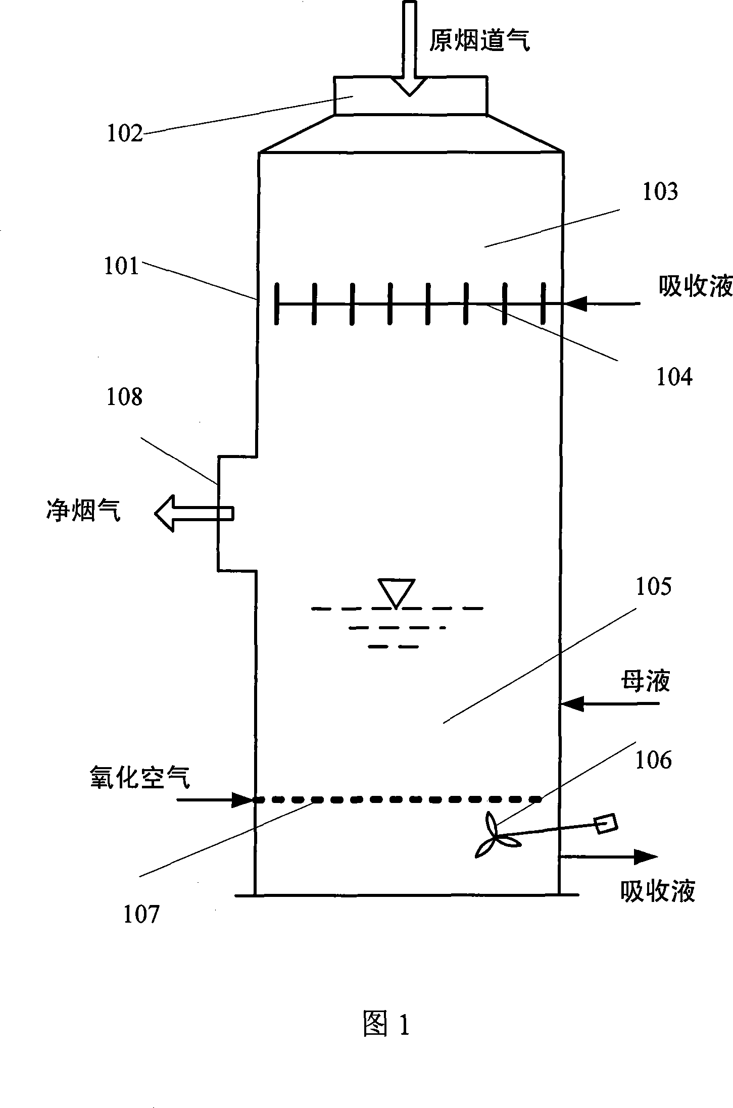
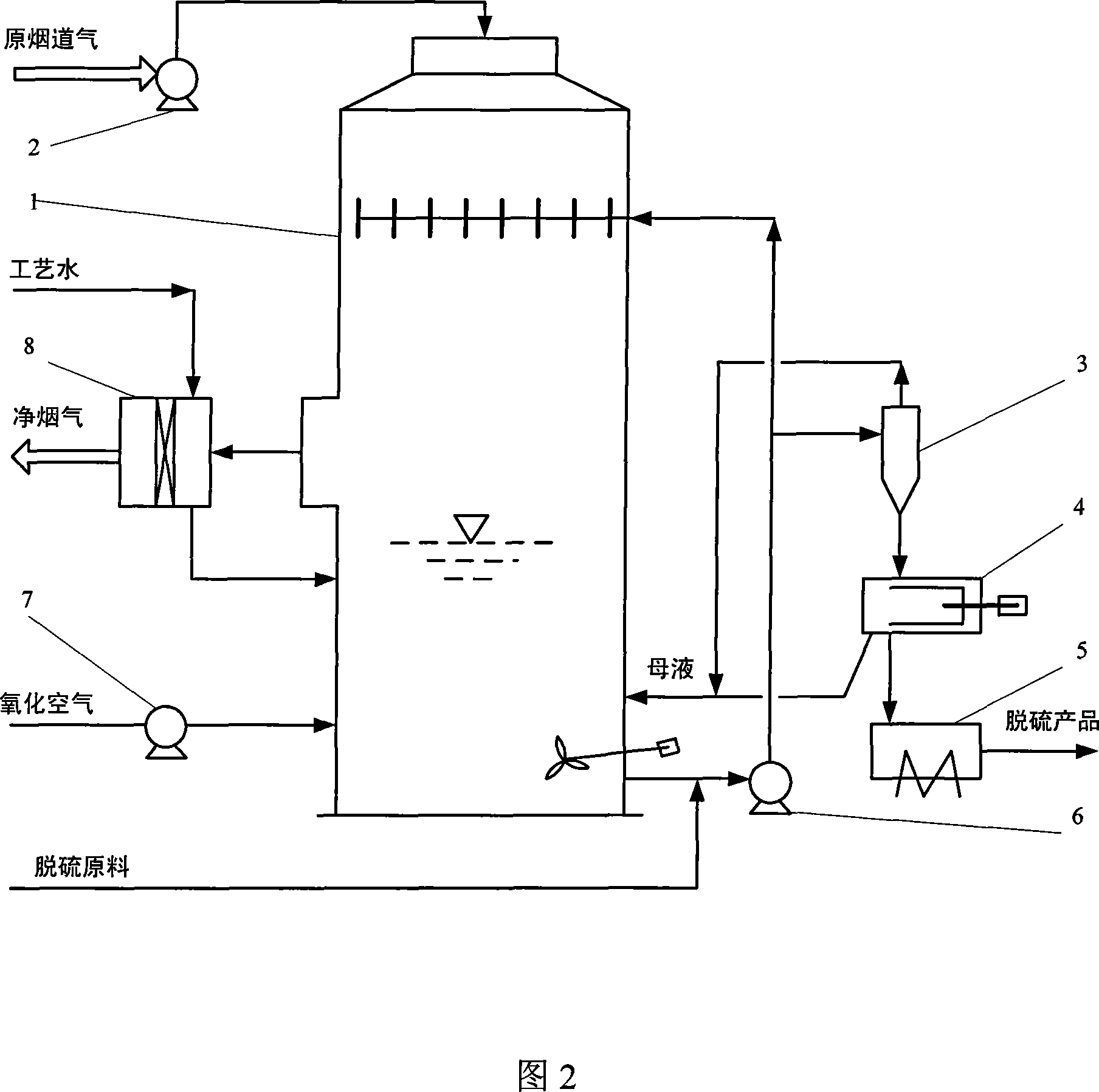
[0101] A booster fan 2, a purification tower 1, a circulation pump 4 (one can also be used as a backup), a set of ammonium sulfate dehydration device 3 (composed of hydrocyclones, centrifuges and dryers), a Oxidation fan 5 (one can also be spared), and a demister 8 arranged in the outlet flue.
[0102]...
Embodiment 2
[0112] Example 1 is desulfurized and purified by calcium method. The raw material for desulfurization is crushed and ground limestone with a particle size of less than 325 mesh and greater than 90%. The limestone slurry with a solid content of 15% of limestone is prepared.
[0113] The by-product of desulfurization is dihydrate gypsum, CaSO4.2H 2 O.
[0114] The main equipment configuration is as follows:
[0115] One booster blower 2, one purification tower 1, one circulation pump 4 (one can also be spared), one set of ammonium sulfate dehydration device 3 (composed of hydrocyclone and vacuum filter), one oxidation blower 5 (one can also be spared), and the demister 8 arranged in the outlet flue.
[0116] The size of the purification tower 1 is the same as in Embodiment 1.
[0117] The tower body 101 of the purification tower 1 is made of glass fiber reinforced plastic, namely FRP material.
[0118] The desulfurization raw material is supplemented on the inlet pipeline of...
Embodiment 3
[0126] Example 1 is desulfurized and purified by the magnesium method. The raw material for desulfurization is magnesium oxide, and the particle size is less than 150 mesh and greater than 90%. It is prepared into a magnesium oxide slurry with a solid content of 15%.
[0127] Desulfurization by-product is magnesium sulfate heptahydrate, MgSO4.7H 2 O.
[0128] The main equipment configuration is as follows:
[0129] A booster blower 2, a purification tower 1, a circulating pump 4 (one can also be spared), a set of ammonium sulfate dehydration device 3 (by hydrocyclone and centrifuge), an oxidation blower 5 ( Also can spare one), and the demister 8 arranged in the outlet flue.
[0130] The size of the purification tower 1 is the same as in Embodiment 1.
[0131] The tower body 101 of the purification tower 1 is made of glass fiber reinforced plastic, namely FRP material.
[0132] The desulfurization raw material is supplemented on the inlet pipeline of the circulating pump, ...
PUM
 Abstract
Description
Claims
Application Information