Composite film separation nitrogen-preparing system and method for well drilling technique

A membrane separation system and composite membrane technology, applied in the field of industrial machinery manufacturing, can solve problems such as damage to the homogeneous membrane membrane tube, poor high temperature resistance of the homogeneous membrane, difficulty in quality control, etc. Large, anti-pollution effect

Inactive Publication Date: 2008-01-09
张星
View PDF0 Cites 5 Cited by
  • Summary
  • Abstract
  • Description
  • Claims
  • Application Information

AI Technical Summary

Problems solved by technology

The disadvantage of this device is: the production process includes a purification (deoxygenation) process, which requires the addition of hydrogen and steam to provide a suitable temperature to achieve the purpose of hydrogen-oxygen reaction to remove oxygen, so more equipment is required, and the overall volume Large, inconvenient to install and move, and greatly affected by external factors, the purity of nitrogen is not easy to control
[0004] In addition, there are also homogeneous membrane nitrogen production equipment. This equipment also includes air coolers, air filter groups, and nitrogen separation systems. Nitrogen is separated, this method is less affected by external factors, and the purity of nitrogen is relatively high. The solidified product is completed by on-site assembly, so it is bulky, inconvenient to move, and has certain difficulties in quality control; in addition, the high temperature resistance of the homogeneous film is poor, and sometimes the air temperature is high during field operations. After passing through the cooler, the temperature is still very high (or the cooler does not work due to power failure), which will cause certain damage to the homogeneous film membrane tube (if the gas is stopped at this time, it may cause accidents such as pipe sticking), thereby shortening the life of the equipment. So this kind of equipment is not suitable for harsh working environment

Method used


Image

  • Composite film separation nitrogen-preparing system and method for well drilling technique
  • Composite film separation nitrogen-preparing system and method for well drilling technique

Examples


Embodiment Construction

[0024] The present invention will be further described below in conjunction with accompanying drawing:

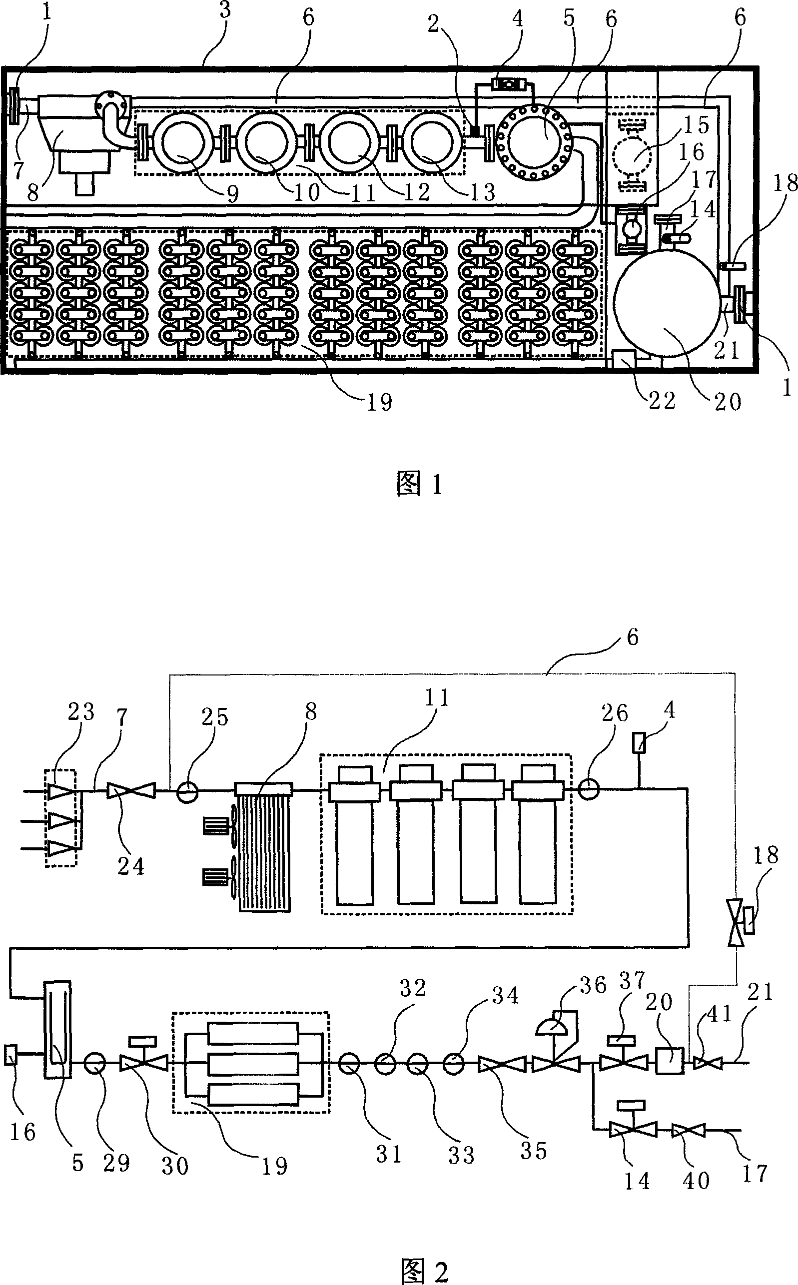
[0025] As shown in Figure 1, the novel membrane separation nitrogen production system used in the drilling process in the present invention includes an air pretreatment system, a nitrogen membrane separation system and a nitrogen drilling process automatic control system, under the control of the nitrogen drilling process automatic control system , compressed air is output through an air pretreatment system and a nitrogen membrane separation system, and all equipment is placed in a box-type skid body 3; the air pretreatment system consists of a compressed air intake pipe 7, an air cooler 8, and an air filter group 11 It is connected with the air heater 5 in turn through a gas pipe; the nitrogen membrane separation system is composed of a composite membrane tube assembly 19 and a nitrogen output pipeline system; the nitrogen drilling process automatic control system is execut...


PUM


Abstract

This invention relates to membrane separation type nitrogen production system used for gas drilling in oil field or natural gas field. It is composed of air pretreatment, membrane separation type nitrogen production and automatic control for drilling process, all of them are placed on a tank like sledge. The air pretreatment system comprises a air cooling unit, a set of filtering apparatus and a heating device successively. Said membrane separation system comprises composed membrane tube assemblies. Said automatic control system comprises programmable automatic control system, containing software of gas drilling process. It controls the main parameters of inlet of separation system of: temperature is not higher than 65 deg.C, pressure is lower than 2.41 MPa, and the oxygen content in outlet is 0.01-5%, with nitrogen production rate of 1800-5400 m3 / h. This invention has advantages of: water-tolerant, high temperature resistance, high pressure resistance, anti-contamination, safety, high efficiency, energy-saving, long service lift, and environmental-protection.

Description

Technical field: [0001] The invention relates to a nitrogen production system and a nitrogen production method, in particular to a composite membrane separation nitrogen production system and a membrane separation nitrogen production method suitable for field operations and used in drilling technology, belonging to the field of industrial machinery manufacturing. Background technique: [0002] Nitrogen is an inert gas, which can be widely used in the operation process of various industrial equipment whose main purpose is to isolate oxygen. Since the air contains about 80% nitrogen, nitrogen is easy to be collected, and then there are A wide variety of nitrogen production systems. [0003] At present, nitrogen has been widely used in the exploitation, completion and workover of oil and gas wells, but its application in oilfield drilling is in its infancy. Facts have proved that nitrogen is very effective for oil field drilling, mainly due to the lack of nitrogen production e...

Claims


Application Information

Patent Timeline
IPC IPC(8): C01B21/02C01B21/04
CPCY02P20/10
Inventor 张星
Owner 张星
Why Eureka
Try Eureka