Chain for use in automobile engine

An automobile engine, a pair of technology, applied in the direction of transmission chain, metal material coating process, coating, etc., can solve the problems of inability to exert durability, promote wear, increase maintenance burden, etc., to suppress abnormal wear extension and improve durability Excellent abrasion resistance and abrasion resistance

Inactive Publication Date: 2008-01-16
TSUBAKIMOTO CHAIN CO
View PDF2 Cites 8 Cited by
  • Summary
  • Abstract
  • Description
  • Claims
  • Application Information

AI Technical Summary

Problems solved by technology

[0010] However, in the transmission small chains for motorcycles and general instruments disclosed in Patent Document 1 above, the surface of the pin is subjected to surface hardening treatment such as boronizing treatment or chromizing treatment, and treatment such as nickel plating. Carburizing, nitriding, etc. are performed on sleeves made of alloy steel such as sintered alloys. However, when used in timing chains of automobile engines, etc., the expected durability cannot be exhibited and abnormal wear elongation occurs. chains, although very few, are reported to exist
[0011] In addition, in the chain for an automobile engine disclosed in the above-mentioned Patent Document 2, the material of the sleeve is carburized, and a vanadium carbide layer (VC) is formed on the surface of the pin to suppress the adhesion due to the sleeve and the pin. However, it is necessary to perform heat treatment on both the sleeve and the pin or to form a vanadium carbide (VC) layer, "increased manufacturing costs", and "lubricating oil" that can be called the fate of metal chains. oil supply”, there is a possibility of increased maintenance burden
[0012] Furthermore, if the surface treatment method of the silent chain disclosed in the above-mentioned Patent Document 3 is used as a chain for an automobile engine, when it is applied to a roller chain or a bush chain, the wear mechanism is uncertain, and the In the sub-chain or bush chain, it is presumed that the inner surface of the bush is corroded by lubricating oil with a high degree of oxidation, and the slip joint between the bush and the pin, which is pressed high under high load, promotes the wear of the sliding surface and cannot to get the same effect as when applied in a silent chain
[0013] Moreover, since the outermost layer of the pin is completely removed by the barreling process, when it is applied to a roller chain or a bush chain in which the inner surface of the bush is in surface contact with the outer surface of the pin, the abrasion powder generated due to abrasion is deposited on the pin and the outer surface of the pin. The existence of inclusions between the sleeves further promotes wear, and the so-called "grinding wear" becomes a cause of abnormal wear of the sliding contact surface between the pin and the sleeve, and improves the wear resistance of the pin. Doesn't behave like it does when applied in a silent chain
[0014] Furthermore, when the pin and the sleeve are made of a material with high affinity, for example, the same element, it is obvious that both are easily bonded to each other, which hinders the smooth bending and sliding of the chain for an automobile engine.

Method used


Image

  • Chain for use in automobile engine
  • Chain for use in automobile engine
  • Chain for use in automobile engine

Examples


Embodiment 1

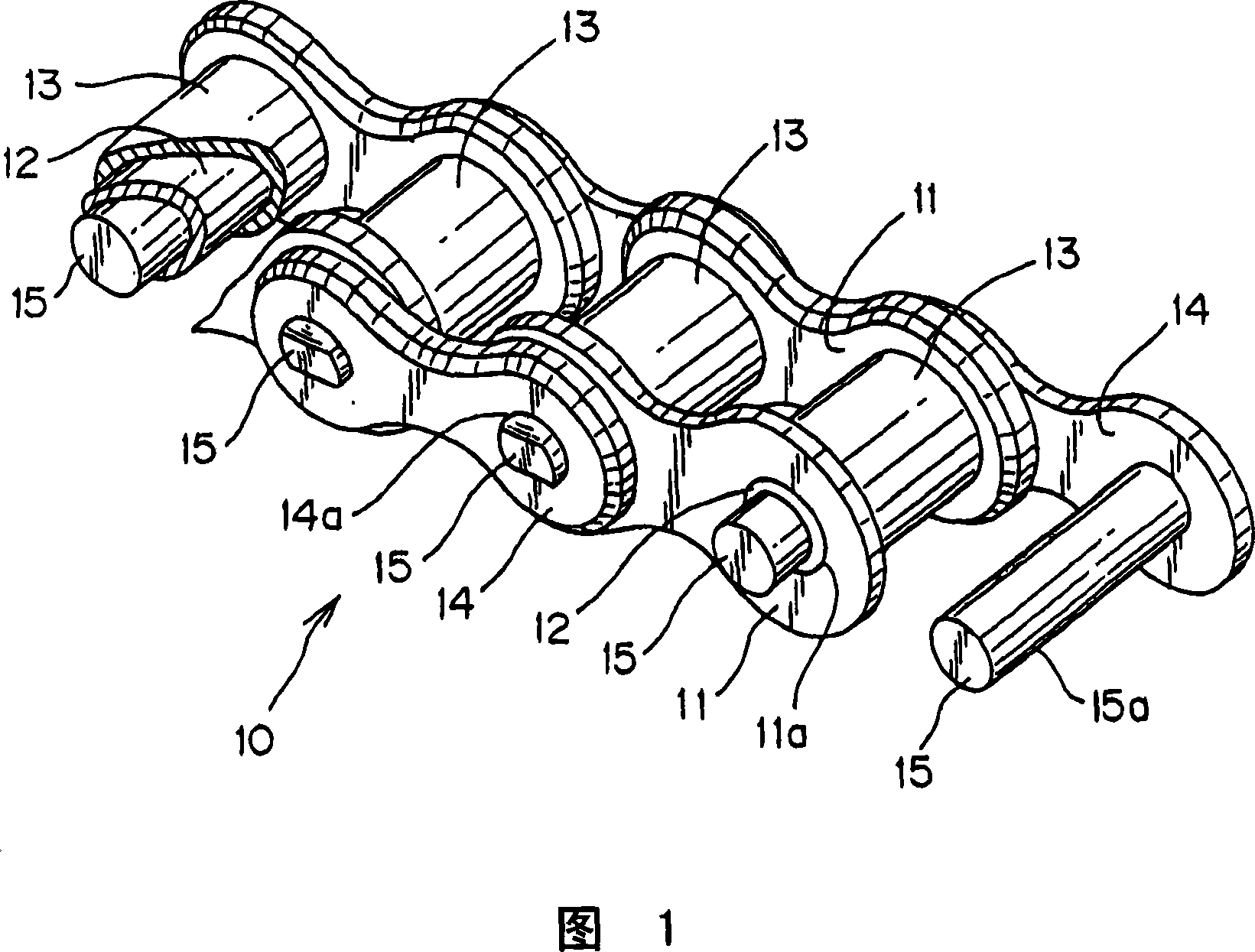
[0043] Fig. 1 is a partial perspective view showing a roller chain according to an embodiment of the present invention. In this FIG. 1 , in order to clarify the internal structure of the roller chain, it is shown in a partially cutaway state.

[0044] In the roller chain 10, both ends of a sleeve 12 are respectively pressed into the sleeve holes 11a of a pair of inner plates 11, and both ends of a pin 15 loosely penetrating through the sleeve 12 are pressed into the pair of inner plates. The pin holes 14a of a pair of outer plates 14 on both outer sides of the plate 11. Furthermore, a roller 13 is rotatably inserted outside the sleeve 12 .

[0045] In the roller chain 10 of the present invention, the sleeve 12 is made of alloy steel, and a high-carbon surface layer is formed on the surface 15 a of steel or low-carbon steel as a base material of the pin 15 . The method of forming this high-carbon surface layer is not particularly limited, but it can be carried out by a so-cal...

Embodiment 2

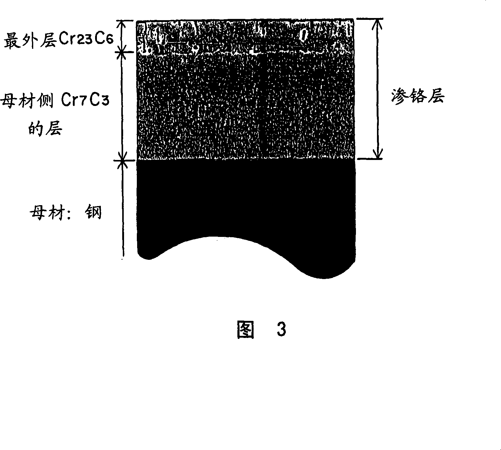
[0061] Based on the automobile engine chain of Example 2, on the basis of the structure of the roller chain of Example 1, the content of Cr was reduced by using barrel grinding treatment. 23 C 6 The surface roughness of the outermost layer of pin 15, containing Cr 23 C 6 The outermost layer is porous (porous), and the exposed part of the porous part becomes a pit, where the liquid is stored and functions, so the "good lubricity" can last for a long time. The "durability" of the child chain. In order to make the surface roughness smaller in this way, by using barrel grinding, the pin as the workpiece and the abrasive rub against each other in the barrel groove, so that small parts such as pins can be efficiently ground.

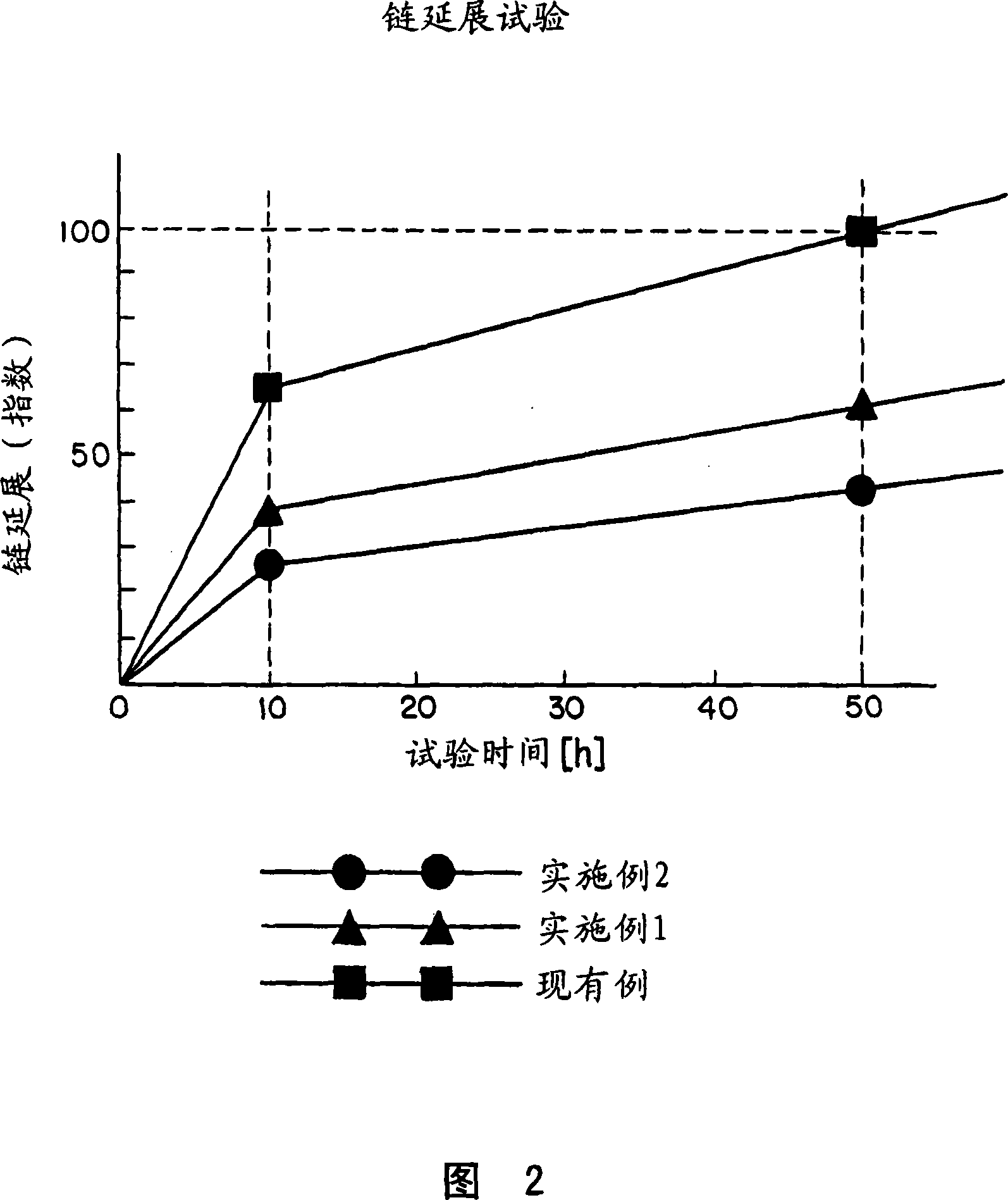
[0062] From the results of the chain elongation test shown in Fig. 2, when the roller chain of Example 2, which has a smaller surface roughness, and the roller chain of the conventional example are compared after 50 hours of the test time, the chain elongat...


PUM

PropertyMeasurementUnit
Vickers hardnessaaaaaaaaaa
thicknessaaaaaaaaaa
thicknessaaaaaaaaaa

Abstract

Connecting pins (15) in a roller chain (10) are chromized by a diffusion penetration treatment, that results in inner and outer chromium carbide layers on the steel base material. The inner layer contains Cr 7 C 3 , and the outermost layer, which is thinner than the inner layer, contains Cr 23 C 6 . The surface roughness of the outer layer is reduced by barrel polishing, without removal of all of the Cr 23 C 6 -containing layer.

Description

technical field [0001] The present invention relates to a chain for power transmission or a chain for driving a camshaft for an automobile engine, and particularly preferably relates to a timing chain for an automobile engine. Background technique [0002] In recent years, due to the requirements of high load, high speed, improvement of layout freedom and maintenance-free, in the power transmission medium used in the camshaft drive mechanism of automobile engine, etc., it has replaced the belt which has been widely used in the past. Toothed belts or V-belts, metal roller chains or metal bush chains with excellent durability are increasingly used. [0003] In general, a metal chain for an automobile engine is configured by pressing both ends of a cylindrical sleeve into the sleeve holes of a pair of inner plates, and inserting a pin loosely penetrating through the sleeve. The two ends are pressed into the pin holes of the pair of outer plates arranged on the two outer sides ...

Claims


Application Information

Patent Timeline
Patent Type & Authority Applications(China)
IPC IPC(8): F16G13/06C23C10/36
CPCF16G13/06
Inventor 永尾宪一户原隆宫泽敏彦
Owner TSUBAKIMOTO CHAIN CO
Why Eureka
Try Eureka