Method for preparing hydrogen and nitrogen by catalytic cracking regenerative fume

A technology for regenerating flue gas and catalytic cracking, applied in chemical instruments and methods, nitrogen preparation, separation methods, etc., can solve the problem of insufficient coking capacity of catalytic cracking unit regenerator, limitation of hydrogen production rate per unit carbon deposition of catalyst, flue gas Insufficient recovery of pressure, etc., to achieve the effect of being beneficial to active protection, reducing coke and dry gas yields, and reducing residence time

Inactive Publication Date: 2008-03-19
高玉玲
View PDF1 Cites 10 Cited by
  • Summary
  • Abstract
  • Description
  • Claims
  • Application Information

AI Technical Summary

Problems solved by technology

[0003] CN1400159A proposes a method for producing hydrogen by using catalytic cracking regenerated flue gas. Although it is different from the currently commonly used methane steam cracking hydrogen production, heavy oil hydrogen production, coal hydrogen production and other methods with high hydrogen costs, but because of its first The carbon-deposited catalyst in the first regenerator reacts with oxygen-containing gas at 500-660°C, the temperature is relatively low, and the first regenerator and the second regenerator are respectively fed with air, and the high-temperature flue gas produced by the second regenerator If it is discharged in another way, not only the pressure of the flue gas cannot be fully recovered, but also the CO in the flue gas produced by the second regenerator 2 And the CO produced by the subsequent medium-temperature conversion of CO 2 It cannot be effectively utilized, that is to say, the ratio of carbon deposits on the catalyst in the first regenerator to CO is not high, so that the hydrogen production rate per unit carbon deposit of the catalyst is limited
[0004] Now, many refineries have the following problems: not only the coking capacity of the regenerator of the catalytic cracking unit is not enough, and urgently needs to be improved, but also the hydrogen production unit needs to be built. How to spend a small amount of money to meet these two problems at the same time?

Method used


Image

  • Method for preparing hydrogen and nitrogen by catalytic cracking regenerative fume
  • Method for preparing hydrogen and nitrogen by catalytic cracking regenerative fume
  • Method for preparing hydrogen and nitrogen by catalytic cracking regenerative fume

Examples


Embodiment 1

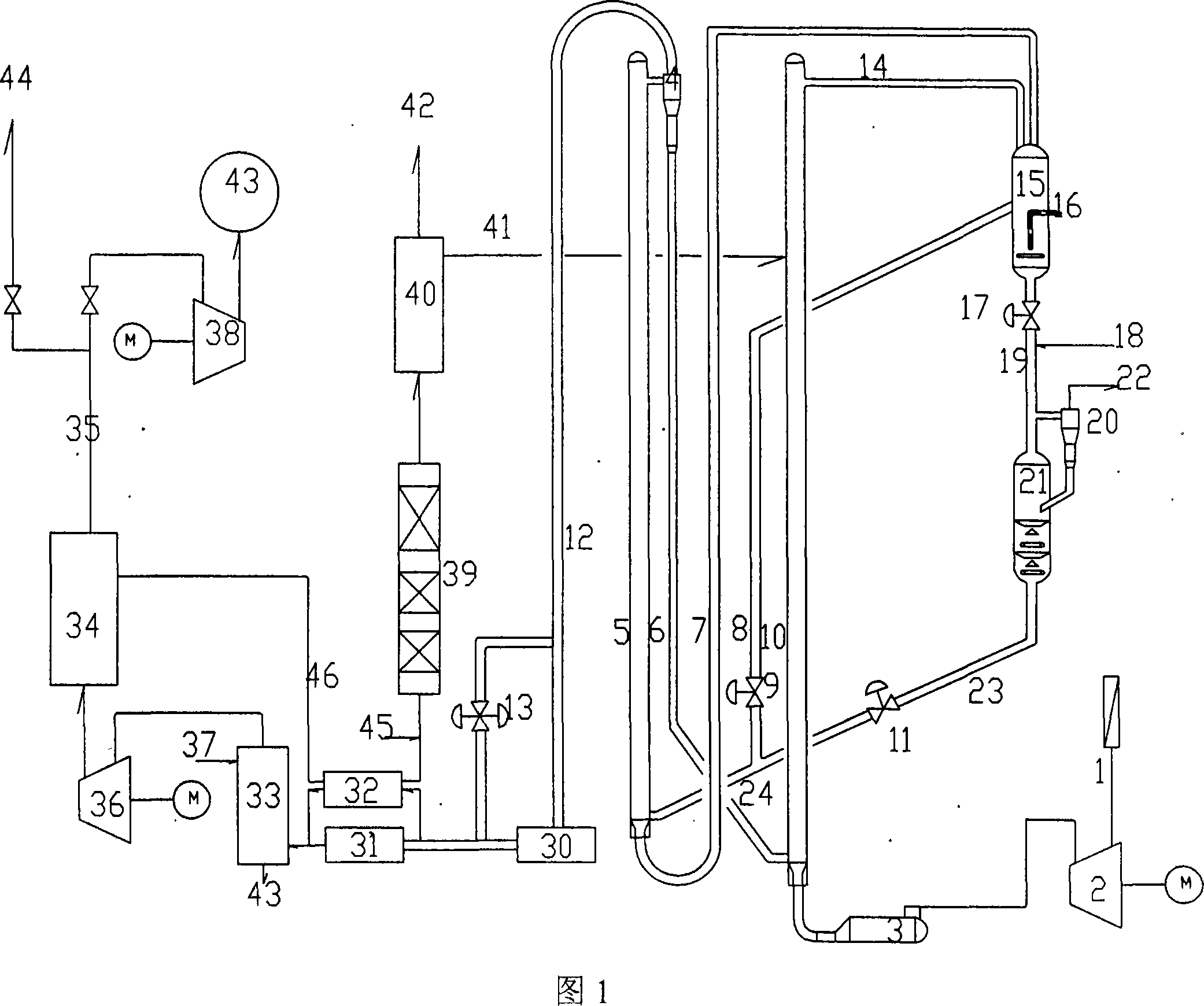
[0039] Embodiment 1: Below in conjunction with Fig. 1, elaborate on the first kind of technical solution of the present invention:

[0040] The charred main air 1 is pressurized by the main air blower 2 and enters the start-up auxiliary heating furnace 3, contacts and burns with the high-temperature semi-regenerated agent from the first regenerator 5 cyclone separator group 4 material legs 6 at the bottom of the second regenerator 10, CO from decarbonization system 40 2 It enters the middle and upper part of the second regenerator through the pipeline 41, and enters the catalyst high-level storage tank 15 through the inverted L pipeline 14 at the top of the second regenerator to realize the separation of the regenerated oxygen-containing flue gas and the regenerant.

[0041] The regenerated agent passes through the regeneration slide valve 17 to the downstream tubular reactor 19 to react with the atomized raw material oil 18, and realizes the separation of the reaction oil gas...

Embodiment 2

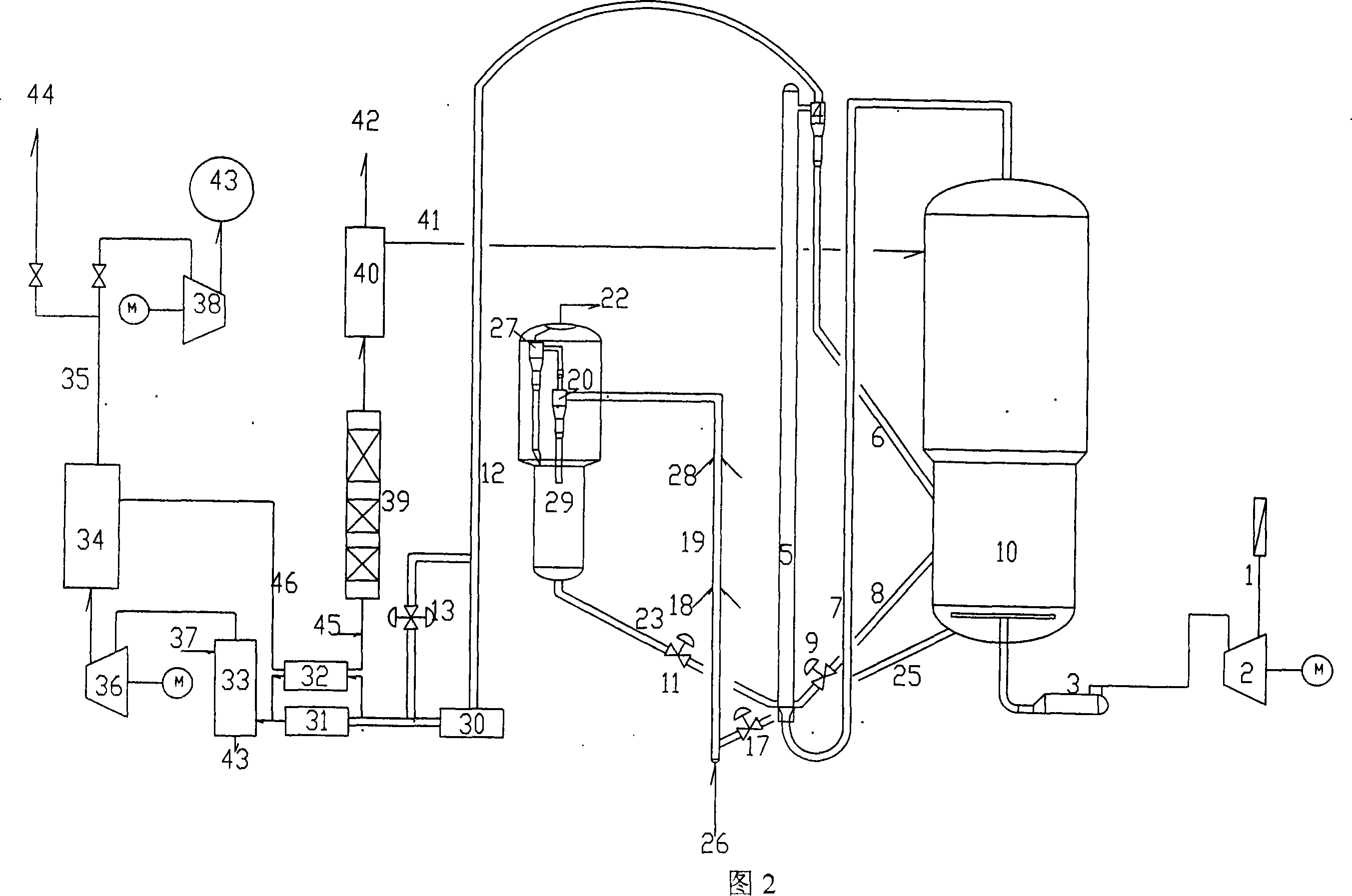
[0055] Embodiment 2: Below in conjunction with Fig. 2, elaborate on the second technical solution of the present invention:

[0056] In Fig. 2, the second regenerator and the catalyst high storage tank in Fig. 1 are replaced with the second regenerator 10, the downcomer reactor in Fig. 1 is replaced with a flexible riser 19, 26 is a lifting medium, and 28 is Refined oil slurry, 25 is the regenerated catalyst pipeline, and others are basically the same as in Fig. 1.

[0057] If the original catalytic cracking unit has a bed regenerator, this bed regenerator can be used as the second regenerator 10, and a tubular regenerator is added as the first regenerator 5; in order to reduce thermal cracking reactions, the original Reaction and settler part to be modified. Scorched main air 1 is pressurized to 0.3-0.45 MPa (absolute pressure) by main air blower 2 and then enters auxiliary heating furnace 3 for start-up, and the temperature of material leg 6 from first regenerator 5 cyclone...

Embodiment 3

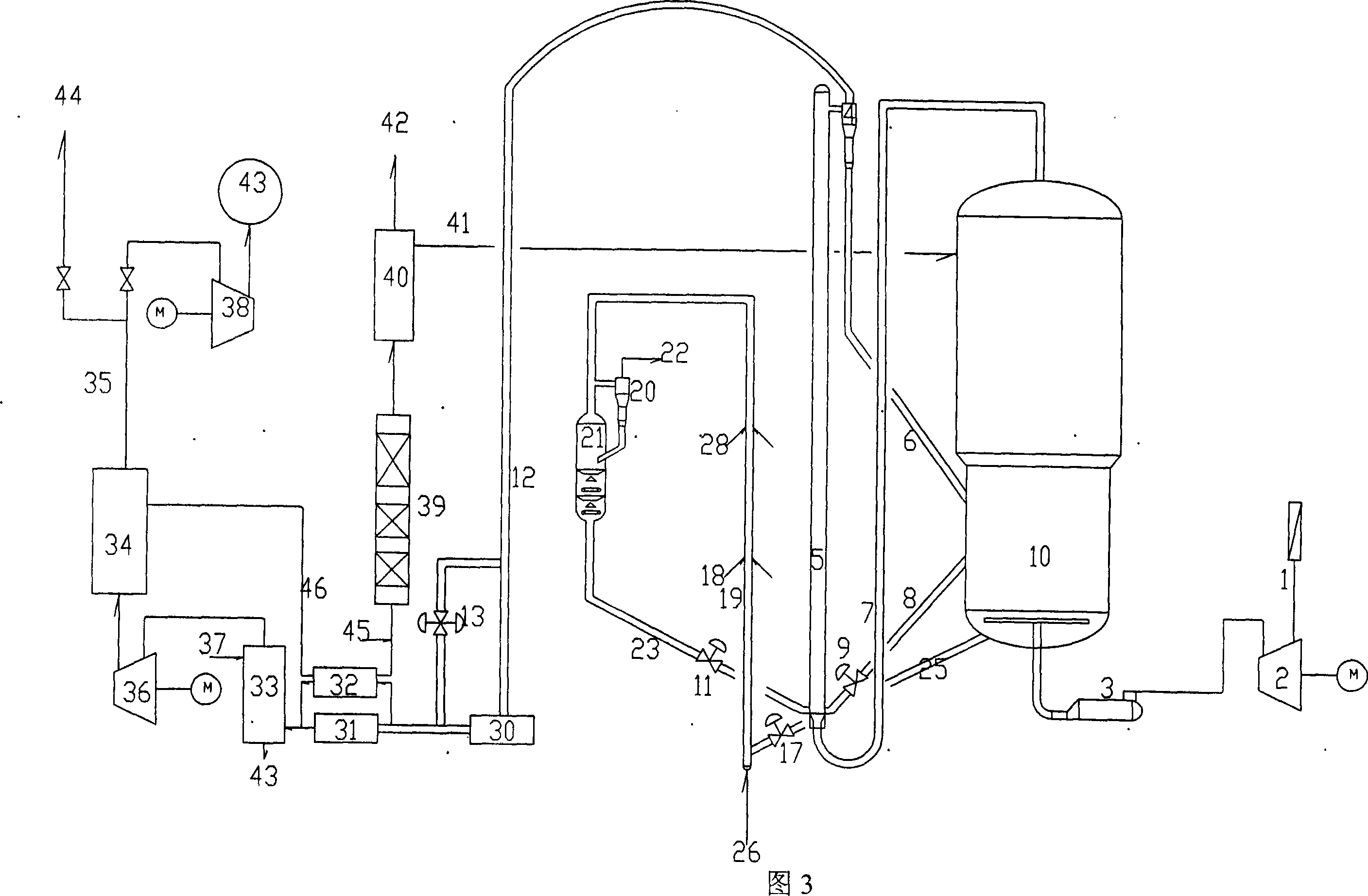
[0061] Embodiment 3: Below in conjunction with Fig. 3, elaborate on the third technical solution of the present invention:

[0062] In Fig. 3, the flexible riser among Fig. 2 is replaced with riser reactor 19, the stripper among Fig. 2 is replaced with currently used settler 29, 20 is coarse cyclone separator, and 27 is primary cyclone Separator, others are basically the same as in Fig. 2.

[0063] If the original catalytic cracking unit has a bed regenerator, this bed regenerator can be used as the second regenerator 10, and a tubular regenerator is added as the first regenerator 5 in addition, and the original reaction and settler 29 parts are not Change. Scorched main air 1 is pressurized to 0.3-0.45 MPa (absolute pressure) by main air blower 2 and then enters auxiliary heating furnace 3 for start-up, and the temperature of material leg 6 from first regenerator 5 cyclone separator group 4 is 670-760°C Preferably, the high-temperature semi-regenerant at 690-730°C is contac...


PUM


Abstract

The invention relates to a method of producing hydrogen and nitrogen by catalytic cracking regenerator gas. The invention has main content that: the high temperature oxygen-contained gas of a second regenerator enters to the bottom of a first regenerator, and is contacted, heated and burnt with a mixing catalyst composed of a carbon deposition catalyst in a self stripper and a regenerant in the second regenerator. The regenerating gas on the upper part of the first regenerator is separated from a half-regenerant by a cyclone separator. The generating gas enters into a pressure energy recovery system, and then enters into the subsequent hydrogen and nitrogen producing process. The half-regenerant enters into the second regenerator through a dipleg, and then is contacted and burnt with full burnt prevailing wind. The stripped carbon deposition catalyst backs into the first regenerator, and then a circulating is formed, in order to effectively use CO and CO2 in the regenerating gas and CO2 produced in the subsequent CO intermediate temperature changing process, and to improve the ratio of the carbon deposition on the first regenerator catalyst transferring into CO, and furthermore to improve the unit carbon deposition hydrogen yield rate of the catalyst.

Description

technical field [0001] The present invention relates to a new catalytic cracking reaction-regeneration technology and the process of using the regenerated flue gas to produce hydrogen and nitrogen. More specifically, it is a technology suitable for existing devices to improve regeneration capacity and light oil yield , is a technology to reduce greenhouse gas emissions and obtain large quantities of cheap hydrogen. Background technique [0002] As we all know, in order to improve the quality of gasoline and diesel, hydrofining has become an indispensable secondary processing method. How to obtain a sufficient amount of cheap hydrogen source is a problem that plagues the oil refining industry. [0003] CN1400159A proposes a method for producing hydrogen by using catalytic cracking regenerated flue gas. Although it is different from the currently commonly used methane steam cracking hydrogen production, heavy oil hydrogen production, coal hydrogen production and other methods ...

Claims


Application Information

Patent Timeline
Patent Type & Authority Applications(China)
IPC IPC(8): B01D53/34C01B3/26C01B3/34C01B21/02
CPCY02P20/151Y02P20/50Y02P20/584
Inventor 高玉玲何燕文
Owner 高玉玲
Why Eureka
Try Eureka